Lexus RX (RX 350L, RX450h) 2016-2026 Repair Manual: Power Window Master Switch
Components
COMPONENTS
ILLUSTRATION
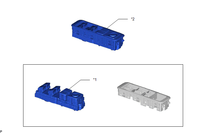
| *1 | MULTIPLEX NETWORK MASTER SWITCH ASSEMBLY | *2 | MULTIPLEX NETWORK MASTER SWITCH ASSEMBLY WITH FRONT DOOR UPPER ARMREST BASE PANEL |
Removal
REMOVAL
PROCEDURE
1. REMOVE MULTIPLEX NETWORK MASTER SWITCH ASSEMBLY WITH FRONT DOOR UPPER ARMREST BASE PANEL
Click here .gif)
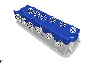
2. REMOVE MULTIPLEX NETWORK MASTER SWITCH ASSEMBLY
| (a) Disengage the 12 claws and remove the multiplex network master switch assembly. |
|
Inspection
INSPECTION
PROCEDURE
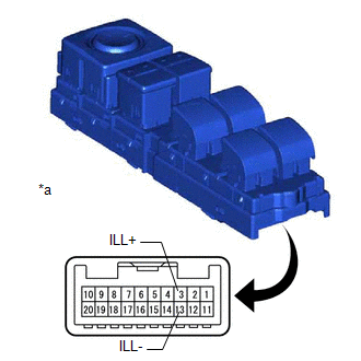
1. INSPECT MULTIPLEX NETWORK MASTER SWITCH ASSEMBLY
| (a) Check that the LED illuminates. (1) Apply battery voltage to the multiplex network master switch assembly and check that the LED illuminates. OK:
If the result is not as specified, replace the multiplex network master switch assembly. |
|
Installation
INSTALLATION
PROCEDURE
1. INSTALL MULTIPLEX NETWORK MASTER SWITCH ASSEMBLY
(a) Engage the 12 claws to install the multiplex network master switch assembly.
2. INSTALL MULTIPLEX NETWORK MASTER SWITCH ASSEMBLY WITH FRONT DOOR UPPER ARMREST BASE PANEL
Click here .gif)
 Jam Protection Function does not Operate
DESCRIPTION This symptom may occur for any of the power windows. The jam protection function operates within a specified range during the manual up or auto up operation. CAUTION / NOTICE / HINT NOTIC ...

Other materials:
Lexus RX (RX 350L, RX450h) 2016-2026 Repair Manual > Parking Assist Monitor System: Steering Angle Initialization Incomplete (C1694)
DESCRIPTION This DTC is stored when the rear television camera assembly judges that the maximum steering angle has not been memorized (steering angle setting is incomplete). DTC No. Detection Item DTC Detection Condition Trouble Area C1694 Steering Angle Initialization Incomplete Ma ...
Lexus RX (RX 350L, RX450h) 2016-2026 Repair Manual > Steering Lock System: Terminals Of Ecu
TERMINALS OF ECU TERMINAL INSPECTION *a Component without harness connected (Steering Lock ECU (Steering Lock Actuator or Upper Bracket Assembly)) - - (a) Measure the voltage and resistance according to the value(s) in the table below. Terminal No. (Symbol) Input/Output Wiring Co ...
Lexus RX (RX 350L, RX450h) 2016-{YEAR} Owners Manual
- For your information
- Pictorial index
- For safety and security
- Instrument cluster
- Operation of each component
- Driving
- Lexus Display Audio system
- Interior features
- Maintenance and care
- When trouble arises
- Vehicle specifications
- For owners
Lexus RX (RX 350L, RX450h) 2016-{YEAR} Repair Manual

0.0267