Lexus RX (RX 350L, RX450h) 2016-2026 Repair Manual: Terminals Of Ecu
TERMINALS OF ECU
CHECK WINDSHIELD WIPER MOTOR ASSEMBLY
(a) Disconnect the i1 windshield wiper motor assembly connector.

(b) Measure the voltage and resistance on the wire harness side connector according to the value(s) in the table below.
| Terminal No. (Symbol) | Wiring Color | Terminal Description | Condition | Specified Condition |
|---|---|---|---|---|
| i1-3 (L) - Body ground | B - Body ground | Engine switch on (IG) signal (Power source circuit) | Engine switch on (IG) | 11 to 14 V |
| Engine switch off | Below 1 V | |||
| i1-4 (+S) - Body ground | W-B - Body ground | Ground | Always | Below 1 Ω |
(c) Reconnect the i1 windshield wiper motor assembly connector.
(d) Measure the voltage and resistance on the wire harness side connector according to the value(s) in the table below.
| Terminal No. (Symbol) | Wiring Color | Terminal Description | Condition | Specified Condition |
|---|---|---|---|---|
| i1-1 (2S) - Body ground | B - Body ground | Windshield wiper motor assembly HI operation signal | Windshield wiper motor assembly stopped | 11 to 14 V |
| Windshield wiper motor assembly operating in HI | Below 1 V | |||
| i1-2 (MPX1) - Body ground | GR - Body ground | LIN communication signal | Engine switch on (IG) | Pulse generation |
HINT:
If the result is not as specified, there may be a malfunction in the wire harness.
CHECK HEADLIGHT ECU SUB-ASSEMBLY RH (for Triple Beam Headlight, for Single Beam Headlight with AFS (Adaptive Front-lighting System))
(a) Measure the voltage according to the value(s) in the table below.
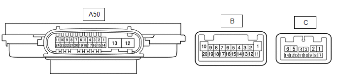
| Terminal No. (Symbol) | Wiring Color | Terminal Description | Condition | Specified Condition |
|---|---|---|---|---|
| A50-7 (HLC) - Body ground | B - Body ground | Headlight cleaner operation signal | Engine switch on (IG), headlight cleaner not operating | 11 to 14 V |
| Engine switch on (IG), headlight cleaner operating | Below 1 V | |||
| A50-18 (FRWA) - Body ground | B - Body ground | Washer switch operation signal | Engine switch on (IG), washer switch off | 11 to 14 V |
| Engine switch on (IG), washer switch on | Below 1 V |
HINT:
Since the A50 headlight ECU sub-assembly RH connector is a waterproof type connector, the voltage and pulses cannot be checked directly. The values listed are for reference only.
CHECK HEADLIGHT ECU SUB-ASSEMBLY RH (for Single Beam Headlight without AFS (Adaptive Front-lighting System))
(a) Measure the voltage according to the value(s) in the table below.
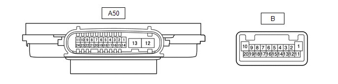
| Terminal No. (Symbol) | Wiring Color | Terminal Description | Condition | Specified Condition |
|---|---|---|---|---|
| A50-7 (HLC) - Body ground | B - Body ground | Headlight cleaner operation signal | Engine switch on (IG), headlight cleaner not operating | 11 to 14 V |
| Engine switch on (IG), headlight cleaner operating | Below 1 V | |||
| A50-18 (FRWA) - Body ground | B - Body ground | Washer switch operation signal | Engine switch on (IG), washer switch off | 11 to 14 V |
| Engine switch on (IG), washer switch on | Below 1 V |
HINT:
Since the A50 headlight ECU sub-assembly RH connector is a waterproof type connector, the voltage and pulses cannot be checked directly. The values listed are for reference only.
 Problem Symptoms Table
PROBLEM SYMPTOMS TABLE HINT: Use the table below to help determine the cause of problem symptoms. If multiple suspected areas are listed, the potential causes of the symptoms are listed in order of pr ...
 Dtc Check / Clear
DTC CHECK / CLEAR CHECK DTC (a) Connect the Techstream to the DLC3. (b) Turn the engine switch on (IG). (c) Turn the Techstream on. (d) Enter the following menus: Body Electrical / (desired system) / ...
Other materials:
Lexus RX (RX 350L, RX450h) 2016-2026 Repair Manual > Oil Pressure Switch: Removal
REMOVAL PROCEDURE 1. REMOVE FRONT FENDER APRON SEAL RH Click here 2. DRAIN ENGINE OIL Click here 3. REMOVE ENGINE OIL PRESSURE SWITCH ASSEMBLY (a) Disconnect the wire harness protector. *1 Wire Harness Protector (b) Disconnect the engine oil pressure switch assembl ...
Lexus RX (RX 350L, RX450h) 2016-2026 Repair Manual > Lighting System (w/ Automatic Headlight Beam Level Control System): Lost Communication With ECM/PCM "A" Missing Message (U010087,U012587,U012987,U014087)
DESCRIPTION These DTCs are stored if a CAN communication malfunction occurs between the forward recognition camera and other ECUs. DTC No. Detection Item DTC Detection Condition Trouble Area DTC Output from U010087 Lost Communication With ECM/PCM "A" Missing Message The forward re ...
Lexus RX (RX 350L, RX450h) 2016-{YEAR} Owners Manual
- For your information
- Pictorial index
- For safety and security
- Instrument cluster
- Operation of each component
- Driving
- Lexus Display Audio system
- Interior features
- Maintenance and care
- When trouble arises
- Vehicle specifications
- For owners
Lexus RX (RX 350L, RX450h) 2016-{YEAR} Repair Manual

0.0097