Lexus RX (RX 350L, RX450h) 2016-2026 Repair Manual: Left Front Wheel Speed Sensor Circuit Short to Battery (C050012)
DESCRIPTION
Refer to DTC C05001F.
Click here .gif)
| DTC No. | Detection Item | DTC Detection Condition | Trouble Area |
|---|---|---|---|
| C050012 | Left Front Wheel Speed Sensor Circuit Short to Battery | The speed sensor short signal is ON continuously for 0.5 seconds or more. |
|
*: w/ AVS
WIRING DIAGRAM
Click here
CAUTION / NOTICE / HINT
NOTICE:
-
After replacing the skid control ECU (brake actuator assembly), perform "Calibration".
Click here
-
After replacing or removing and installing a speed sensor, perform Dealer Mode (Signal Check) inspection to confirm that the speed sensors are operating correctly.
Click here
PROCEDURE
| 1. | CHECK VEHICLE SPECIFICATION |
(a) Check the vehicle specification.
| Result | Proceed to |
|---|---|
| w/o AVS | A |
| w/ AVS | B |
| B | .gif) | GO TO STEP 5 |
|
.gif)
| 2. | CHECK HARNESS AND CONNECTOR (SENSOR GROUND CIRCUIT) |
| (a) Make sure that there is no looseness at the locking part and the connecting part of the connectors. OK: The connector is securely connected. |
|

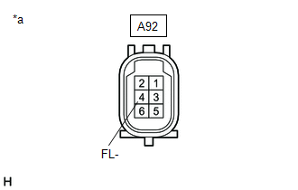
(b) Disconnect the A92 front speed sensor LH connector.
(c) Check both the connector case and the terminals for deformation and corrosion.
OK:
No deformation or corrosion.
(d) Turn the engine switch on (IG).
(e) Measure the voltage according to the value(s) in the table below.
Standard Voltage:
| Tester Connection | Condition | Specified Condition |
|---|---|---|
| A92-3 (FL+) - A92-4 (FL-) | Engine switch on (IG) | 11 to 14 V |
| OK | | REPLACE FRONT SPEED SENSOR LH |
|
| 3. | CHECK HARNESS AND CONNECTOR (SENSOR GROUND CIRCUIT) |
| (a) Turn the engine switch off. |
|
(b) Make sure that there is no looseness at the locking part and the connecting part of the connectors.
OK:
The connector is securely connected.
(c) Disconnect the A41 skid control ECU (brake actuator assembly) connector.
(d) Check both the connector case and the terminals for deformation and corrosion.
OK:
No deformation or corrosion.
(e) Measure the voltage according to the value(s) in the table below.
Standard Voltage:
| Tester Connection | Condition | Specified Condition |
|---|---|---|
| A92-4 (FL-) - Body ground | Always | Below 1.5 V |
| NG | | REPAIR OR REPLACE HARNESS OR CONNECTOR |
|
| 4. | CHECK HARNESS AND CONNECTOR (FRONT SPEED SENSOR LH - BRAKE ACTUATOR ASSEMBLY) |
(a) Measure the resistance according to the value(s) in the table below.
Standard Resistance:
| Tester Connection | Condition | Specified Condition |
|---|---|---|
| A92-3 (FL+) or A41-22 (FL+) - A92-4 (FL-) or A41-21 (FL-) | Always | 10 kΩ or higher |
| OK | | REPLACE BRAKE ACTUATOR ASSEMBLY |
| NG | | REPAIR OR REPLACE HARNESS OR CONNECTOR |
| 5. | CHECK HARNESS AND CONNECTOR (SENSOR GROUND CIRCUIT) |
| (a) Make sure that there is no looseness at the locking part and the connecting part of the connectors. OK: The connector is securely connected. |
|
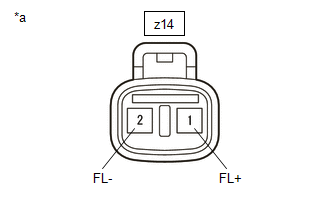
(b) Disconnect the z14 front speed sensor LH connector.
(c) Check both the connector case and the terminals for deformation and corrosion.
OK:
No deformation or corrosion.
(d) Turn the engine switch on (IG).
(e) Measure the voltage according to the value(s) in the table below.
Standard Voltage:
| Tester Connection | Condition | Specified Condition |
|---|---|---|
| z14-1 (FL+) - z14-2 (FL-) | Engine switch on (IG) | 11 to 14 V |
| OK | | REPLACE FRONT SPEED SENSOR LH |
|
| 6. | CHECK HARNESS AND CONNECTOR (SENSOR GROUND CIRCUIT) |
| (a) Turn the engine switch off. |
|
(b) Make sure that there is no looseness at the locking part and the connecting part of the connectors.
OK:
The connector is securely connected.
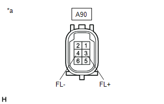
(c) Disconnect the A90 front skid control sensor wire LH connector.
(d) Check both the connector case and the terminals for deformation and corrosion.
OK:
No deformation or corrosion.
(e) Turn the engine switch on (IG).
(f) Measure the voltage according to the value(s) in the table below.
Standard Voltage:
| Tester Connection | Condition | Specified Condition |
|---|---|---|
| A90-3 (FL+) - A90-4 (FL-) | Engine switch on (IG) | 11 to 14 V |
| OK | | REPLACE FRONT SKID CONTROL SENSOR WIRE LH |
|
| 7. | CHECK HARNESS AND CONNECTOR (SENSOR GROUND CIRCUIT) |
| (a) Turn the engine switch off. |
|
(b) Make sure that there is no looseness at the locking part and the connecting part of the connectors.
OK:
The connector is securely connected.
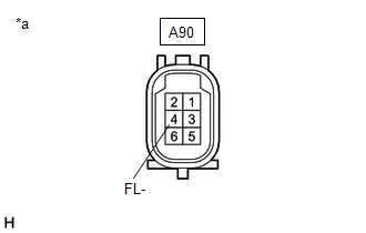
(c) Disconnect the A41 skid control ECU (brake actuator assembly) connector.
(d) Check both the connector case and the terminals for deformation and corrosion.
OK:
No deformation or corrosion.
(e) Measure the voltage according to the value(s) in the table below.
Standard Voltage:
| Tester Connection | Condition | Specified Condition |
|---|---|---|
| A90-4 (FL-) - Body ground | Always | Below 1.5 V |
| NG | | REPAIR OR REPLACE HARNESS OR CONNECTOR |
|
| 8. | CHECK HARNESS AND CONNECTOR (FRONT SKID CONTROL SENSOR WIRE LH - BRAKE ACTUATOR ASSEMBLY) |
(a) Measure the resistance according to the value(s) in the table below.
Standard Resistance:
| Tester Connection | Condition | Specified Condition |
|---|---|---|
| A90-3 (FL+) or A41-22 (FL+) - A90-4 (FL-) or A41-21 (FL-) | Always | 10 kΩ or higher |
| OK | | REPLACE BRAKE ACTUATOR ASSEMBLY |
| NG | | REPAIR OR REPLACE HARNESS OR CONNECTOR |
 Yaw Rate Sensor Signal Stuck In Range (C00632A,C05201C,C05202A,C052096)
DESCRIPTION for Optitron Meter Type:
The airbag sensor assembly has a built-in yaw rate and acceleration sensor and detects the vehicle condition.
These DTCs are stored when the skid control ECU (b ...
 Left Front Wheel Speed Sensor Circuit Short to Ground or Open (C050014)
DESCRIPTION Refer to DTC C05001F. Click here DTC No. Detection Item DTC Detection Condition Trouble Area C050014 Left Front Wheel Speed Sensor Circuit Short to Ground or Open An ope ...
Other materials:
Lexus RX (RX 350L, RX450h) 2016-2026 Repair Manual > Navigation System: Registered Device cannot be Deleted
PROCEDURE 1. DELETE OPERATION (a) Check if a registered portable player can be deleted normally. OK: Registered portable player can be deleted normally. OK END NG PROCEED TO NEXT SUSPECTED AREA SHOWN IN PROBLEM SYMPTOMS TABLE ...
Lexus RX (RX 350L, RX450h) 2016-2026 Repair Manual > Airbag System: Front Door Pressure Sensor RH (B166C,B166F)
DESCRIPTION The side collision sensor RH circuit (bus 1) consists of the airbag sensor assembly, door side airbag sensor RH and rear airbag sensor RH. The door side airbag sensor RH and rear airbag sensor RH detect impacts to the vehicle and send signals to the airbag sensor assembly to determine if ...
Lexus RX (RX 350L, RX450h) 2016-{YEAR} Owners Manual
- For your information
- Pictorial index
- For safety and security
- Instrument cluster
- Operation of each component
- Driving
- Lexus Display Audio system
- Interior features
- Maintenance and care
- When trouble arises
- Vehicle specifications
- For owners
Lexus RX (RX 350L, RX450h) 2016-{YEAR} Repair Manual

0.0123