Lexus RX (RX 350L, RX450h) 2016-2025 Repair Manual: Left Front Wheel Speed Sensor Circuit Short to Ground or Open (C050014)
DESCRIPTION
Refer to DTC C05001F.
Click here .gif)
| DTC No. | Detection Item | DTC Detection Condition | Trouble Area |
|---|---|---|---|
| C050014 | Left Front Wheel Speed Sensor Circuit Short to Ground or Open | An open in the speed sensor signal circuit continues for 0.5 seconds or more. |
|
*: w/ AVS
WIRING DIAGRAM
Click here
CAUTION / NOTICE / HINT
NOTICE:
-
After replacing the skid control ECU (brake actuator assembly), perform "Calibration".
Click here
-
After replacing or removing and installing a speed sensor, perform Dealer Mode (Signal Check) inspection to confirm that the speed sensors are operating correctly.
Click here
PROCEDURE
| 1. | READ VALUE USING TECHSTREAM (MOMENTARY INTERRUPTION) |
(a) Connect the Techstream to the DLC3.
(b) Turn the engine switch on (IG).
(c) Enter the following menus: Chassis / Brake/EPB / Data List.
Chassis > Brake/EPB > Data List| Tester Display | Measurement Item | Range | Normal Condition | Diagnostic Note |
|---|---|---|---|---|
| FL Speed Open | Front speed sensor LH open detection | Under intermittent / Normal | Under intermittent: Momentary interruption detected Normal: Momentary interruption not detected | - |
| Tester Display |
|---|
| FL Speed Open |
(d) Select the line graph display.
(e) Check for any momentary interruption in the wire harness and connector.
Click here
OK:
Normal (There are no momentary interruptions.)
NOTICE:
Perform the above inspection before removing the sensor and connector.
| NG | .gif) | GO TO STEP 5 |
|
.gif)
| 2. | READ VALUE USING TECHSTREAM (FL WHEEL SPEED) |
(a) Enter the following menus: Chassis / Brake/EPB / Data List.
Chassis > Brake/EPB > Data List| Tester Display | Measurement Item | Range | Normal Condition | Diagnostic Note |
|---|---|---|---|---|
| FL Wheel Speed | Front wheel speed sensor LH reading | Min.: 0.0 km/h (0.0 mph) Max.: 6553.5 km/h (4072 mph) | Vehicle stopped: 0.0 km/h (0.0 mph) | When driving at constant speed: No large fluctuations |
| Tester Display |
|---|
| FL Wheel Speed |
(b) Start the engine.
(c) Perform a road test.
(d) Check the speed value output from the speed sensor displayed on the Techstream.
HINT:
Factors that affect the indicated vehicle speed include tire size, tire pressure, and tire wear. The speed indicated on the speedometer has an allowable margin of error. This can be tested using a speedometer tester (calibrated chassis dynamometer). For details about testing and the margin of error, see the reference chart.
Click here
OK:
The speed value output from the speed sensor displayed on the Techstream is similar to the speed indicated on the speedometer.
| NG | | GO TO STEP 5 |
|
| 3. | CLEAR DTC |
(a) Operate the Techstream to clear the codes. Enter the following menus: Chassis / Brake/EPB / Trouble Codes.
Chassis > Brake/EPB > Clear DTCs(b) Press the DTC clear button.
(c) Turn the engine switch off.
|
| 4. | RECONFIRM DTC |
(a) Start the engine.
(b) Perform a road test.
(c) Read the DTCs following the prompts on the Techstream. Enter the following menus: Chassis / Brake/EPB / Trouble Codes.
Chassis > Brake/EPB > Trouble Codes(d) Check if the same DTC is output.
| Result | Proceed to |
|---|---|
| DTC C050014 is not output. | A |
| DTC C050014 is output. | B |
| A | | USE SIMULATION METHOD TO CHECK |
| B | | REPLACE BRAKE ACTUATOR ASSEMBLY |
| 5. | CHECK VEHICLE SPECIFICATION |
(a) Check the vehicle specification.
| Result | Proceed to |
|---|---|
| w/o AVS | A |
| w/ AVS | B |
| B | | GO TO STEP 8 |
|
| 6. | INSPECT HARNESS AND CONNECTOR (FRONT SPEED SENSOR LH - BRAKE ACTUATOR ASSEMBLY) |
(a) Turn the engine switch off.
(b) Make sure that there is no looseness at the locking part and the connecting part of the connectors.
OK:
The connector is securely connected.
(c) Disconnect the A41 skid control ECU (brake actuator assembly) connector.
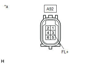
(d) Disconnect the A92 front speed sensor LH connector.
(e) Check both the connector case and the terminals for deformation and corrosion.
OK:
No deformation or corrosion.
(f) Measure the resistance according to the value(s) in the table below.
Standard Resistance:
| Tester Connection | Condition | Specified Condition |
|---|---|---|
| A92-3 (FL+) - A41-22 (FL+) | Always | Below 1 Ω |
| A92-3 (FL+) or A41-22 (FL+) - Body ground | Always | 10 kΩ or higher |
| A92-4 (FL-) - A41-21 (FL-) | Always | Below 1 Ω |
| A92-4 (FL-) or A41-21 (FL-) - Body ground | Always | 10 kΩ or higher |
| NG | | REPAIR OR REPLACE HARNESS OR CONNECTOR |
|
| 7. | INSPECT BRAKE ACTUATOR ASSEMBLY (SENSOR POWER SOURCE CIRCUIT) |
| (a) Reconnect the A41 skid control ECU (brake actuator assembly) connector. |
|
(b) Make sure that there is no looseness at the locking part and the connecting part of the connectors.
OK:
The connector is securely connected.
(c) Turn the engine switch on (IG).
(d) Measure the voltage according to the value(s) in the table below.
Standard Voltage:
| Tester Connection | Condition | Specified Condition |
|---|---|---|
| A92-3 (FL+) - Body ground | Engine switch on (IG) | 11 to 14 V |
| OK | | REPLACE FRONT SPEED SENSOR LH |
| NG | | REPLACE BRAKE ACTUATOR ASSEMBLY |
| 8. | INSPECT FRONT SKID CONTROL SENSOR WIRE LH |
| (a) Turn the engine switch off. |
|
(b) Make sure that there is no looseness at the locking part and the connecting part of the connectors.
OK:
The connector is securely connected.
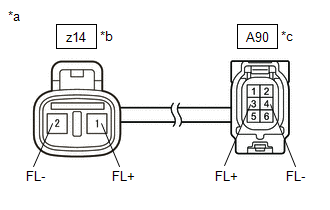
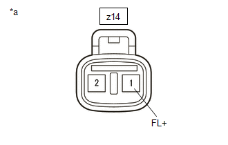
(c) Disconnect the z14 and A90 front skid control sensor wire LH connector.
(d) Check both the connector case and the terminals for deformation and corrosion.
OK:
No deformation or corrosion.
(e) Measure the resistance according to the value(s) in the table below.
Standard Resistance:
| Tester Connection | Condition | Specified Condition |
|---|---|---|
| z14-1 (FL+) - A90-3 (FL+) | Always | Below 1 Ω |
| z14-1 (FL+) or A90-3 (FL+) - Body ground and other terminals | Always | 10 kΩ or higher |
| z14-2 (FL-) - A90-4 (FL-) | Always | Below 1 Ω |
| z14-2 (FL-) or A90-4 (FL-) - Body ground and other terminals | Always | 10 kΩ or higher |
| NG | | REPLACE FRONT SKID CONTROL SENSOR WIRE LH |
|
| 9. | CHECK HARNESS AND CONNECTOR (FRONT SKID CONTROL SENSOR WIRE LH - BRAKE ACTUATOR ASSEMBLY) |
(a) Make sure that there is no looseness at the locking part and the connecting part of the connectors.
OK:
The connector is securely connected.
(b) Disconnect the A41 skid control ECU (brake actuator assembly) connector.
(c) Check both the connector case and the terminals for deformation and corrosion.
OK:
No deformation or corrosion.
(d) Measure the resistance according to the value(s) in the table below.
Standard Resistance:
| Tester Connection | Condition | Specified Condition |
|---|---|---|
| A90-3 (FL+) - A41-22 (FL+) | Always | Below 1 Ω |
| A90-3 (FL+) or A41-22 (FL+) - Body ground | Always | 10 kΩ or higher |
| A90-4 (FL-) - A41-21 (FL-) | Always | Below 1 Ω |
| A90-4 (FL-) or A41-21 (FL-) - Body ground | Always | 10 kΩ or higher |
| NG | | REPAIR OR REPLACE HARNESS OR CONNECTOR |
|
| 10. | INSPECT BRAKE ACTUATOR ASSEMBLY (SENSOR POWER SOURCE CIRCUIT) |
| (a) Reconnect the A41 skid control ECU (brake actuator assembly) connector. |
|
(b) Reconnect the A90 front skid control sensor wire LH connector.
(c) Make sure that there is no looseness at the locking part and the connecting part of the connectors.
OK:
The connector is securely connected.
(d) Turn the engine switch on (IG).
(e) Measure the voltage according to the value(s) in the table below.
Standard Voltage:
| Tester Connection | Condition | Specified Condition |
|---|---|---|
| z14-1 (FL+) - Body ground | Engine switch on (IG) | 11 to 14 V |
| OK | | REPLACE FRONT SPEED SENSOR LH |
| NG | | REPLACE BRAKE ACTUATOR ASSEMBLY |
 Left Front Wheel Speed Sensor Circuit Short to Battery (C050012)
DESCRIPTION Refer to DTC C05001F. Click here DTC No. Detection Item DTC Detection Condition Trouble Area C050012 Left Front Wheel Speed Sensor Circuit Short to Battery The speed sen ...
 Left Front Wheel Speed Sensor Circuit Intermittent (C05001F)
DESCRIPTION The speed sensor detects wheel speed and sends the appropriate signals to the skid control ECU (brake actuator assembly). These signals are used for brake control. Speed sensor rotors have ...
Other materials:
Lexus RX (RX 350L, RX450h) 2016-2025 Repair Manual > Rear Seat Inner Belt Assembly(for Lh Side): Removal
REMOVAL CAUTION / NOTICE / HINT The necessary procedures (adjustment, calibration, initialization or registration) that must be performed after parts are removed and installed, or replaced during rear seat inner belt assembly removal/installation are shown below. Necessary Procedure After Parts Remo ...
Lexus RX (RX 350L, RX450h) 2016-2025 Owners Manual > Opening, closing and locking the doors: Smart access system with
push-button start
The following operations can be performed simply by carrying the
electronic
key on your person, for example in your pocket. The driver should always
carry the electronic key.
Locks and unlocks the doors
Locks and unlocks the back door
Starts and stops the hybrid system
■ Antenna l ...
Lexus RX (RX 350L, RX450h) 2016-{YEAR} Owners Manual
- For your information
- Pictorial index
- For safety and security
- Instrument cluster
- Operation of each component
- Driving
- Lexus Display Audio system
- Interior features
- Maintenance and care
- When trouble arises
- Vehicle specifications
- For owners
Lexus RX (RX 350L, RX450h) 2016-{YEAR} Repair Manual

0.017