Lexus RX (RX 350L, RX450h) 2016-2026 Repair Manual: Washer Fluid Level Warning Switch Circuit
DESCRIPTION
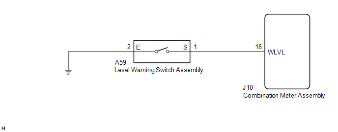
When the washer fluid level is lower than a certain level, a warning message is displayed on the combination meter assembly.
WIRING DIAGRAM
CAUTION / NOTICE / HINT
NOTICE:
Inspect the fuses of circuits related to this system before performing the following procedure.
PROCEDURE
| 1. | READ VALUE USING TECHSTREAM |
(a) Connect the Techstream to the DLC3.
(b) Turn the engine switch on (IG).
(c) Turn the Techstream on.
(d) Enter the following menus: Body Electrical / Combination Meter / Data List.
(e) Read the Data List according to the display on the Techstream.
Body Electrical > Combination Meter > Data List| Tester Display | Measurement Item | Range | Normal Condition | Diagnostic Note |
|---|---|---|---|---|
| Washer Switch | Washer fluid level warning switch | ON or OFF | ON: Washer fluid level low OFF: Washer fluid level not low | - |
| Tester Display |
|---|
| Washer Switch |
OK:
The Techstream display changes correctly in response to the washer fluid level.
| OK | .gif) | GO TO METER / GAUGE SYSTEM |
|
.gif)
| 2. | CHECK HARNESS AND CONNECTOR (LEVEL WARNING SWITCH ASSEMBLY - COMBINATION METER ASSEMBLY) |
(a) Disconnect the A59 level warning switch assembly connector.
(b) Measure the voltage according to the value(s) in the table below.
Standard Voltage:
| Tester Connection | Condition | Specified Condition |
|---|---|---|
| A59-1 (S) - Body ground | Engine switch off | Below 1 V |
| A59-1 (S) - Body ground | Engine switch on (IG) | 11 to 14 V |
| NG | | GO TO STEP 4 |
|
| 3. | CHECK HARNESS AND CONNECTOR (LEVEL WARNING SWITCH ASSEMBLY - BODY GROUND) |
(a) Measure the resistance according to the value(s) in the table below.
Standard Resistance:
| Tester Connection | Condition | Specified Condition |
|---|---|---|
| A59-2 (E) - Body ground | Always | Below 1 Ω |
| OK | | REPLACE LEVEL WARNING SWITCH ASSEMBLY |
| NG | | REPAIR OR REPLACE HARNESS OR CONNECTOR |
| 4. | CHECK HARNESS AND CONNECTOR (WASHER MOTOR AND PUMP ASSEMBLY - WINDSHIELD WIPER SWITCH ASSEMBLY) |
(a) Disconnect the J10 combination meter assembly connector.
(b) Measure the resistance according to the value(s) in the table below.
Standard Resistance:
| Tester Connection | Condition | Specified Condition |
|---|---|---|
| A59-1 (S) - J10-16 (WLVL) | Always | Below 1 Ω |
| A59-1 (S) or J10-16 (WLVL) - Body ground | Always | 10 kΩ or higher |
| OK | | REPLACE COMBINATION METER ASSEMBLY |
.gif)
| NG | | REPAIR OR REPLACE HARNESS OR CONNECTOR |
 Washer Motor Circuit
DESCRIPTION When the washer motor and pump assembly receives signals from the windshield wiper switch assembly it operates to spray washer fluid from the washer nozzle sub-assemblies. WIRING DIAGRAM ...
 Wiper Switch
...
Other materials:
Lexus RX (RX 350L, RX450h) 2016-2026 Repair Manual > Audio And Visual System (for 12.3 Inch Display): Extension Module Malfunction 2 (B1556)
DESCRIPTION This DTC is stored when a malfunction occurs in the Navigation ECU. DTC No. Detection Item DTC Detection Condition Trouble Area B1556 Extension Module Malfunction 2 When any of the following conditions is met:
Internal power supply malfunction
Internal hard drive ma ...
Lexus RX (RX 350L, RX450h) 2016-2026 Repair Manual > Window Defogger System: Rear Window Defogger System does not Operate
DESCRIPTION When the rear window defogger switch on the radio receiver assembly is pressed, the operation signal is transmitted to the air conditioning amplifier assembly via CAN communication. When the air conditioning amplifier assembly receives the signal, it turns on the semiconductor pwr integr ...
Lexus RX (RX 350L, RX450h) 2016-{YEAR} Owners Manual
- For your information
- Pictorial index
- For safety and security
- Instrument cluster
- Operation of each component
- Driving
- Lexus Display Audio system
- Interior features
- Maintenance and care
- When trouble arises
- Vehicle specifications
- For owners
Lexus RX (RX 350L, RX450h) 2016-{YEAR} Repair Manual

0.0093