Lexus RX (RX 350L, RX450h) 2016-2026 Repair Manual: Installation
INSTALLATION
PROCEDURE
1. INSTALL BACK DOOR LOCK ASSEMBLY
HINT:
Make sure to remove the string before installing a new back door lock assembly.
(a) Apply MP grease to the sliding parts of the back door lock assembly.
(b) Engage the clip to temporarily install the back door lock assembly as shown in the illustration.
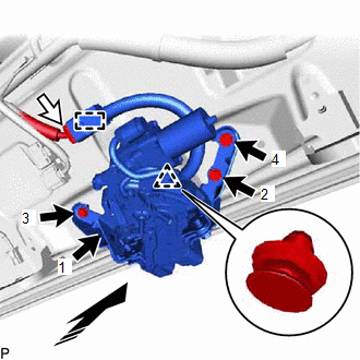
.png) | Install in this Direction |
(c) Install the back door lock assembly with the 4 bolts.
HINT:
Tighten the bolts in the order shown in the illustration.
Torque:
12.5 N·m {127 kgf·cm, 9 ft·lbf}
(d) Engage the clamp.
(e) Connect the connector.
2. INSTALL BACK DOOR TRIM PANEL ASSEMBLY (w/o Rear No. 2 Seat)
Click here .gif)
3. INSTALL BACK DOOR TRIM PANEL ASSEMBLY (w/ Rear No. 2 Seat)
Click here
4. INSTALL NO. 1 LUGGAGE COMPARTMENT LIGHT ASSEMBLY
Click here
5. INSTALL DOOR PULL HANDLE
Click here
6. INSTALL BACK DOOR TRIM BASE
Click here
7. INSTALL BACK DOOR LOCK COVER (w/o Rear No. 2 Seat)
Click here
8. INSTALL BACK DOOR LOCK COVER (w/ Rear No. 2 Seat)
Click here
9. INSTALL BACK DOOR TRIM COVER LH (w/o Rear No. 2 Seat)
Click here
10. INSTALL BACK DOOR TRIM COVER LH (w/ Rear No. 2 Seat)
Click here
11. INSTALL BACK DOOR TRIM COVER RH
HINT:
Use the same procedure as for the LH side.
12. INSTALL BACK WINDOW UPPER PANEL TRIM (w/o Rear No. 2 Seat)
Click here
13. INSTALL BACK WINDOW UPPER PANEL TRIM (w/ Rear No. 2 Seat)
Click here
14. INSPECT POWER BACK DOOR SYSTEM
Click here
15. INSPECT BACK DOOR CLOSER SYSTEM
Click here
 Inspection
INSPECTION PROCEDURE 1. INSPECT BACK DOOR LOCK ASSEMBLY *a Clockwise *b Counterclockwise *c Over-latch *d Full-latch *e Half-latch *f Open-latch *g Component ...

Other materials:
Lexus RX (RX 350L, RX450h) 2016-2026 Repair Manual > Automatic High Beam Main Switch: Removal
REMOVAL PROCEDURE 1. REMOVE INSTRUMENT PANEL GARNISH LH Click here 2. REMOVE FRONT DOOR SCUFF PLATE LH Click here 3. REMOVE COWL SIDE TRIM BOARD LH Click here 4. REMOVE NO. 1 INSTRUMENT PANEL UNDER COVER SUB-ASSEMBLY Click here 5. DISCONNECT HOOD LOCK CONTROL LEVER SUB-ASSEMBLY C ...
Lexus RX (RX 350L, RX450h) 2016-2026 Repair Manual > Climate Control Seat System: On-vehicle Inspection
ON-VEHICLE INSPECTION PROCEDURE 1. CHECK AIR DUCT (a) Check that there are no cracks or damage on the air ducts of the seat climate control blower and seatback climate control blower, and that the air ducts are installed correctly. 2. CHECK CLIMATE CONTROL SEAT SYSTEM (a) Turn the engine switch on ( ...
Lexus RX (RX 350L, RX450h) 2016-{YEAR} Owners Manual
- For your information
- Pictorial index
- For safety and security
- Instrument cluster
- Operation of each component
- Driving
- Lexus Display Audio system
- Interior features
- Maintenance and care
- When trouble arises
- Vehicle specifications
- For owners
Lexus RX (RX 350L, RX450h) 2016-{YEAR} Repair Manual

0.0111