Lexus RX (RX 350L, RX450h) 2016-2024 Repair Manual: All Doors LOCK/UNLOCK Functions do not Operate Via Door Control Switch
DESCRIPTION
The main body ECU (multiplex network body ECU) receives switch signals from the power window regulator switch assembly on the front passenger door and activates the door lock motor on each door according to these signals.
WIRING DIAGRAM

CAUTION / NOTICE / HINT
NOTICE:
-
Before replacing the main body ECU (multiplex network body ECU), refer to Registration.
Click here
.gif)
PROCEDURE
| 1. | READ VALUE USING TECHSTREAM (Door Lock SW-Lock, Door Lock SW-Unlock) |
(a) Connect the Techstream to the DLC3.
(b) Turn the engine switch on (IG).
(c) Turn the Techstream on.
(d) Enter the following menus: Body Electrical / Main Body / Data List.
(e) Read the Data List according to the display on the Techstream.
Body Electrical > Main Body > Data List| Tester Display | Measurement Item | Range | Normal Condition | Diagnostic Note |
|---|---|---|---|---|
| Door Lock SW-Lock | Power window regulator switch assembly lock signal | OFF or ON | OFF: Lock side of power window regulator switch assembly not pushed ON: Lock side of power window regulator switch assembly pushed | - |
| Door Lock SW-Unlock | Power window regulator switch assembly unlock signal | OFF or ON | OFF: Unlock side of power window regulator switch assembly not pushed ON: Unlock side of power window regulator switch assembly pushed | - |
| Tester Display |
|---|
| Door Lock SW-Lock |
| Door Lock SW-Unlock |
OK:
The Techstream indicates ON or OFF according to the switch operation shown in the table.
| OK | .gif) | REPLACE MAIN BODY ECU (MULTIPLEX NETWORK BODY ECU) |
|
.gif)
| 2. | INSPECT POWER WINDOW REGULATOR SWITCH ASSEMBLY |
(a) Remove the power window regulator switch assembly.
Click here
(b) Inspect the power window regulator switch assembly.
Click here
| NG | | REPLACE POWER WINDOW REGULATOR SWITCH ASSEMBLY |
|
| 3. | CHECK HARNESS AND CONNECTOR (POWER WINDOW REGULATOR SWITCH ASSEMBLY -INSTRUMENT PANEL JUNCTION BLOCK ASSEMBLY) |
(a) Disconnect the 2A and 2B instrument panel junction block assembly connectors.
(b) Measure the resistance according to the value(s) in the table below.
Standard Resistance:
| Tester Connection | Condition | Specified Condition |
|---|---|---|
| M6-7 (UL) - 2A-39 | Always | Below 1 Ω |
| M6-12 (L) - 2B-16 | Always | Below 1 Ω |
| M6-5 (GND) - Body ground | Always | Below 1 Ω |
| 2A-39 or M6-7 (UL) - Body ground | Always | 10 kΩ or higher |
| 2B-16 or M6-12 (L) - Body ground | Always | 10 kΩ or higher |
| NG | | REPAIR OR REPLACE HARNESS OR CONNECTOR |
|
| 4. | INSPECT INSTRUMENT PANEL JUNCTION BLOCK ASSEMBLY |
(a) Remove the instrument panel junction block assembly.
Click here
(b) Remove the main body ECU (multiplex network body ECU).
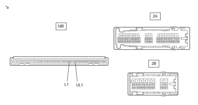
| *a | Component without harness connected (Instrument Panel Junction Block Assembly) | - | - |
(c) Measure the resistance according to the value(s) in the table below.
Standard Resistance:
| Tester Connection | Condition | Specified Condition |
|---|---|---|
| MB-22 (UL1) - 2A-39 | Always | Below 1 Ω |
| MB-20 (L1) - 2B-16 | Always | Below 1 Ω |
| OK | | REPLACE MAIN BODY ECU (MULTIPLEX NETWORK BODY ECU) |
| NG | | REPLACE INSTRUMENT PANEL JUNCTION BLOCK ASSEMBLY |
 GSW Terminal Circuit Malfunction (B1243)
DESCRIPTION If the collision door lock release function does not operate normally, or an open or short in the GSW input circuit of the main body ECU (multiplex network body ECU) is detected, DTC B1243 ...
 Rear Door Lock
...
Other materials:
Lexus RX (RX 350L, RX450h) 2016-2024 Repair Manual > Audio And Visual System (for 8 Inch Display): AVC-LAN Circuit
DESCRIPTION Each unit of the audio and visual system connected to the AVC-LAN (communication bus) transmits signals via AVC-LAN communication. If a short to +B or short to ground occurs in an AVC-LAN communication line, the audio and visual system will not function normally because communication is ...
Lexus RX (RX 350L, RX450h) 2016-2024 Repair Manual > Sfi System: Fuel Rail / System Pressure - Too High (P008800)
DESCRIPTION Refer to DTC P008700. Click here DTC No. Detection Item DTC Detection Condition Trouble Area MIL Memory Note P008800 Fuel Rail / System Pressure - Too High Although the ECM is requesting the fuel pump assembly (for high pressure side) to open the spill control va ...
Lexus RX (RX 350L, RX450h) 2016-{YEAR} Owners Manual
- For your information
- Pictorial index
- For safety and security
- Instrument cluster
- Operation of each component
- Driving
- Lexus Display Audio system
- Interior features
- Maintenance and care
- When trouble arises
- Vehicle specifications
- For owners
Lexus RX (RX 350L, RX450h) 2016-{YEAR} Repair Manual

0.018