Lexus RX (RX 350L, RX450h) 2016-2026 Repair Manual: AVC-LAN Circuit
DESCRIPTION
Each unit of the audio and visual system connected to the AVC-LAN (communication bus) transmits signals via AVC-LAN communication.
If a short to +B or short to ground occurs in an AVC-LAN communication line, the audio and visual system will not function normally because communication is not possible.
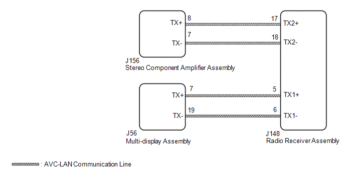
WIRING DIAGRAM
CAUTION / NOTICE / HINT
NOTICE:
Depending on the parts that are replaced during vehicle inspection or maintenance, performing initialization, registration or calibration may be needed. Refer to Precaution for Audio and Visual System.
Click here .gif)
HINT:
The radio receiver assembly is the master unit.
PROCEDURE
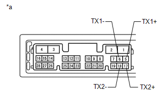
| 1. | INSPECT RADIO RECEIVER ASSEMBLY |
(a) Remove the radio receiver assembly.
Click here
| (b) Measure the resistance according to the value(s) in the table below. Standard Resistance:
|
|
| NG | .gif) | REPLACE RADIO RECEIVER ASSEMBLY |
|
.gif)
| 2. | CHECK HARNESS AND CONNECTOR (AVC-LAN CIRCUIT) |
(a) Disconnect the J148 radio receiver assembly connector.
(b) Disconnect the J156 stereo component amplifier assembly connector.
(c) Disconnect the J56 multi-display assembly connector.
(d) Measure the resistance according to the value(s) in the table below.
Standard Resistance:
| Tester Connection | Condition | Specified Condition |
|---|---|---|
| J148-17 (TX2+) - J156-8 (TX+) | Always | Below 1 Ω |
| J148-18 (TX2-) - J156-7 (TX-) | Always | Below 1 Ω |
| J148-5 (TX1+) - J56-7 (TX+) | Always | Below 1 Ω |
| J148-6 (TX1-) - J56-19 (TX-) | Always | Below 1 Ω |
| J148-17 (TX2+) or J156-8 (TX+) - Body ground | Always | 10 kΩ or higher |
| J148-18 (TX2-) or J156-7 (TX-) - Body ground | Always | 10 kΩ or higher |
| J148-5 (TX1+) or J56-7 (TX+) - Body ground | Always | 10 kΩ or higher |
| J148-6 (TX1-) or J56-19(TX-) - Body ground | Always | 10 kΩ or higher |
| NG | | REPAIR OR REPLACE HARNESS OR CONNECTOR |
|
| 3. | INSPECT MALFUNCTIONING PARTS |
(a) Disconnect and reconnect each slave unit one by one until the master unit returns to normal.
HINT:
- Check all slave units.
- If disconnecting a slave unit causes the master unit to return to normal, the slave unit is defective and should be replaced.
OK:
Master unit returns to normal.
| OK | | REPLACE MALFUNCTIONING PARTS |
| NG | | REPLACE RADIO RECEIVER ASSEMBLY |
 Mute Signal Circuit between Stereo Component Amplifier and Telematics Transceiver
DESCRIPTION The DCM (telematics transceiver) sends a mute signal to the stereo component amplifier assembly. The stereo component amplifier assembly controls the volume according to the mute signal fr ...
 Vehicle Speed Signal Circuit between Stereo Component Amplifier and Combination Meter
DESCRIPTION The stereo component amplifier assembly receives a vehicle speed signal from the combination meter assembly to control the ASL function. HINT:
A voltage of 12 V or 5 V is output from ea ...
Other materials:
Lexus RX (RX 350L, RX450h) 2016-2026 Repair Manual > Combination Meter: Reassembly
REASSEMBLY PROCEDURE 1. INSTALL COMBINATION METER GLASS (for Optitron Meter Type) (a) Engage the 8 claws to install the combination meter glass. 2. INSTALL COMBINATION METER GLASS (for TFT Meter Type) (a) Engage the 9 claws to install the combination meter glass. ...
Lexus RX (RX 350L, RX450h) 2016-2026 Repair Manual > Vehicle Stability Control System: Left Rear Wheel Speed Sensor Circuit Intermittent (C050C1F)
DESCRIPTION The speed sensor detects wheel speed and sends the appropriate signals to the skid control ECU (brake actuator assembly). These signals are used for brake control. Speed sensor rotors have rows of alternating N and S magnetic poles, and their magnetic fields change when the rotors turn. ...
Lexus RX (RX 350L, RX450h) 2016-{YEAR} Owners Manual
- For your information
- Pictorial index
- For safety and security
- Instrument cluster
- Operation of each component
- Driving
- Lexus Display Audio system
- Interior features
- Maintenance and care
- When trouble arises
- Vehicle specifications
- For owners
Lexus RX (RX 350L, RX450h) 2016-{YEAR} Repair Manual

0.0115