Lexus RX (RX 350L, RX450h) 2016-2026 Repair Manual: Mute Signal Circuit between Stereo Component Amplifier and Telematics Transceiver
DESCRIPTION
The DCM (telematics transceiver) sends a mute signal to the stereo component amplifier assembly.
The stereo component amplifier assembly controls the volume according to the mute signal from the DCM (telematics transceiver).
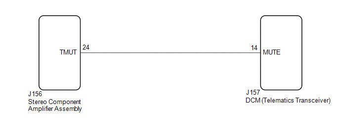
WIRING DIAGRAM
CAUTION / NOTICE / HINT
NOTICE:
-
Depending on the parts that are replaced during vehicle inspection or maintenance, performing initialization, registration or calibration may be needed. Refer to Precaution for Audio and Visual System.
Click here
.gif)
-
Before replacing the DCM (telematics transceiver), refer to Registration.
Click here
PROCEDURE
| 1. | INSPECT DCM (TELEMATICS TRANSCEIVER) |
| (a) Measure the voltage according to the value(s) in the table below. Standard Voltage:
|
|
| OK |  | PROCEED TO NEXT SUSPECTED AREA SHOWN IN PROBLEM SYMPTOMS TABLE |
|

| 2. | CHECK HARNESS AND CONNECTOR (STEREO COMPONENT AMPLIFIER ASSEMBLY - DCM (TELEMATICS TRANSCEIVER)) |
(a) Disconnect the J156 stereo component amplifier assembly connector.
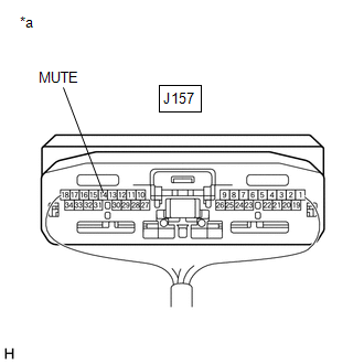
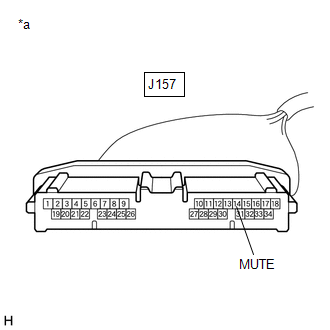
(b) Disconnect the J157 DCM (telematics transceiver) connector.
(c) Measure the resistance according to the value(s) in the table below.
Standard Resistance:
| Tester Connection | Condition | Specified Condition |
|---|---|---|
| J156-24 (TMUT) - J157-14 (MUTE) | Always | Below 1 Ω |
| J156-24 (TMUT) or J157-14 (MUTE) - Body ground | Always | 10 kΩ or higher |
| NG | | REPAIR OR REPLACE HARNESS AND CONNECTOR |
|
| 3. | INSPECT STEREO COMPONENT AMPLIFIER ASSEMBLY |
(a) Reconnect the J156 stereo component amplifier assembly connector.
| (b) Measure the voltage according to the value(s) in the table below. Standard Voltage:
|
|
| OK | | REPLACE DCM (TELEMATICS TRANSCEIVER) |
| NG | | REPLACE STEREO COMPONENT AMPLIFIER ASSEMBLY |
 Mute Signal Circuit between Radio Receiver and Stereo Component Amplifier
DESCRIPTION This circuit sends a signal to the stereo component amplifier assembly to mute noise. Due to this, the noise produced by changing the sound source ceases. If there is an open in the circui ...
 AVC-LAN Circuit
DESCRIPTION Each unit of the audio and visual system connected to the AVC-LAN (communication bus) transmits signals via AVC-LAN communication. If a short to +B or short to ground occurs in an AVC-LAN ...
Other materials:
Lexus RX (RX 350L, RX450h) 2016-2026 Repair Manual > Charging System: Charging Failure
PROCEDURE 1. CHECK GENERATOR PULLEY WITH CLUTCH (ON-VEHICLE INSPECTION) (a) Start the engine and visually check that the generator rotor assembly (fan) in the generator assembly is operating. OK: The generator rotor assembly (fan) is operating. NG REPLACE GENERATOR PULLEY WITH CLUTC ...
Lexus RX (RX 350L, RX450h) 2016-2026 Repair Manual > Airbag System: Short in Knee Airbag (D Side) Squib Circuit (B1860-B1863)
DESCRIPTION The driver side knee airbag squib circuit consists of the airbag sensor assembly and lower No. 1 instrument panel airbag assembly. The airbag sensor assembly uses this circuit to deploy the airbag when deployment conditions are met. These DTCs are stored when a malfunction is detected in ...
Lexus RX (RX 350L, RX450h) 2016-{YEAR} Owners Manual
- For your information
- Pictorial index
- For safety and security
- Instrument cluster
- Operation of each component
- Driving
- Lexus Display Audio system
- Interior features
- Maintenance and care
- When trouble arises
- Vehicle specifications
- For owners
Lexus RX (RX 350L, RX450h) 2016-{YEAR} Repair Manual

0.0093