Lexus RX (RX 350L, RX450h) 2016-2026 Repair Manual: Terminals Of Ecu
TERMINALS OF ECU
CHECK INSTRUMENT PANEL JUNCTION BLOCK ASSEMBLY AND MAIN BODY ECU (MULTIPLEX NETWORK BODY ECU)
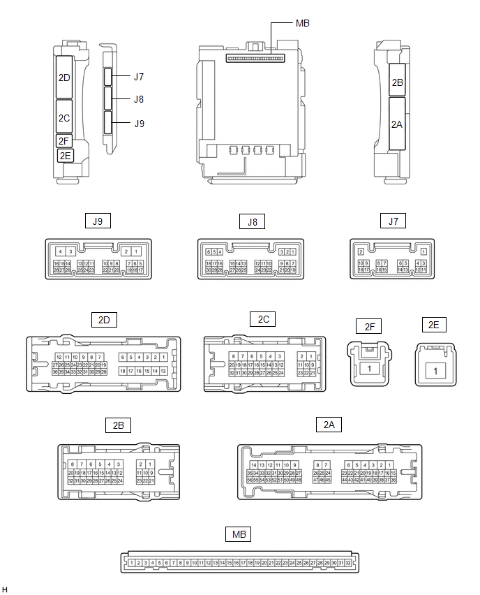
(a) Disconnect the instrument panel junction block assembly and main body ECU (multiplex network body ECU) connectors.
(b) Measure the voltage on the wire harness side connector according to the value(s) in the table below.
| Terminal No. | Wiring Color | Terminal Description | Condition | Specified Condition |
|---|---|---|---|---|
| 2C-1 - Body ground | W - Body ground | Battery power supply | Always | 11 to 14 V |
| 2E-1 - Body ground | B - Body ground | Battery power supply | Always | 11 to 14 V |
If the result is not as specified, there may be a malfunction in the wire harness.
(c) Measure the resistance on the wire harness side connector according to the value(s) in the table below.
| Terminal No. (Symbol) | Wiring Color | Terminal Description | Condition | Specified Condition |
|---|---|---|---|---|
| 2B-3 - Body ground | W-B - Body ground | Ground | Always | Below 1 Ω |
If the result is not as specified, there may be a malfunction in the wire harness.
(d) Reconnect the instrument panel junction block assembly and main body ECU (multiplex network body ECU) connectors.
(e) Measure the voltage and check for pulses according to the value(s) in the table below.
| Terminal No. (Symbol) | Wiring Color | Terminal Description | Condition | Specified Condition |
|---|---|---|---|---|
| 2A-30 - Body ground | GR - Body ground | ACC power supply | Engine switch on (ACC) | 11 to 14 V |
| Engine switch off | Below 1 V | |||
| 2A-17 - Body ground | G - Body ground | IG power supply | Engine switch on (IG) | 11 to 14 V |
| Engine switch off | Below 1 V | |||
| 2B-27 - Body ground | LA-G - Body ground | Footwell light, instrument panel box light and instrument panel ambient illumination light power supply | Always | 11 to 14 V |
| 2B-25 - Body ground*2 | Y - Body ground | Door ambient illumination light LH power supply | Always | 11 to 14 V |
| 2B-24 - Body ground*2 | L - Body ground | Door ambient illumination light RH power supply | Always | 11 to 14 V |
| 2D-19 - Body ground | B - Body ground | No. 1 luggage compartment light power supply | DOME CUT relay on | 11 to 14 V |
| DOME CUT relay off | Below 1 V | |||
| 2B-9 - Body ground | L - Body ground |
| DOME CUT relay on | 11 to 14 V |
| DOME CUT relay off | Below 1 V | |||
| 2B-10 - Body ground | W - Body ground | Map light assembly, courtesy light RH and vanity lights power supply | DOME CUT relay on | 11 to 14 V |
| DOME CUT relay off | Below 1 V | |||
| 2B-29 - Body ground | GR - Body ground | Interior lights drive output | Interior lights off (when operated by illuminated entry system) | 11 to 14 V |
| Interior lights on (when operated by illuminated entry system) | Below 1 V | |||
| 2A-37 - Body ground | W - Body ground | Footwell light and instrument panel box light output | Footwell light and instrument panel box light off | 11 to 14 V |
| Footwell light and instrument panel box light dimmer control operating (dimming) | Pulse generation | |||
| Footwell light and instrument panel box light at full brightness | Below 2.2 V | |||
| J9-27 (DMDR) - Body ground | BE - Body ground | Door switch signal input | Door switch on | Below 1 V |
| Door switch off | Pulse generation | |||
| J9-28 (DMON) - Body ground | LG - Body ground | Front dome light switch signal input | Front dome light switch on | Below 1 V |
| Front dome light switch off | Pulse generation | |||
| 2D-24 - Body ground | W - Body ground | Rear door courtesy light switch LH input | Rear door LH open | Below 1 V |
| Rear door LH closed | 11 to 14 V | |||
| 2A-31 - Body ground | R - Body ground | Rear door courtesy light switch RH input | Rear door RH open | Below 1 V |
| Rear door RH closed | 11 to 14 V | |||
| J8-6 (FLCY) - Body ground | P - Body ground | Front door courtesy light switch LH input | Front door LH open | Below 1 V |
| Front door LH closed | 11 to 14 V | |||
| J8-27 (FRCY) - Body ground | R - Body ground | Front door courtesy light switch RH input | Front door RH open | Below 1 V |
| Front door RH closed | 11 to 14 V | |||
| J9-2 (LSWR) - Body ground | L - Body ground | Rear door unlock detection switch RH input | Rear door RH locked | Pulse generation |
| Rear door RH unlocked | Below 1 V | |||
| 2B-14 - Body ground | V - Body ground | Rear door unlock detection switch LH input | Rear door LH locked | Pulse generation |
| Rear door LH unlocked | Below 1 V | |||
| 2B-13 - Body ground | B - Body ground | Front door unlock detection switch LH input | Front door LH locked | Pulse generation |
| Front door LH unlocked | Below 1 V | |||
| 2B-12 - Body ground | P - Body ground | Front door unlock detection switch RH input | Front door RH locked | Pulse generation |
| Front door RH unlocked | Below 1 V | |||
| J7-1 (RCYL) - Body ground | G - Body ground | Rear door courtesy light RH drive output | Rear door courtesy light RH off | 11 to 14 V |
| Rear door courtesy light RH on | Below 1 V | |||
| J7-2 (LCYL) - Body ground | Y - Body ground | Rear door courtesy light LH drive output | Rear door courtesy light LH off | 11 to 14 V |
| Rear door courtesy light LH on | Below 1 V | |||
| J9-17 (FRCL) - Body ground | SB - Body ground | Front door courtesy light RH drive output | Front door courtesy light RH off | 11 to 14 V |
| Front door courtesy light RH on | Below 1 V | |||
| J9-1 (FLCL) - Body ground | W - Body ground | Front door courtesy light LH drive output | Front door courtesy light LH off | 11 to 14 V |
| Front door courtesy light LH on | Below 1 V | |||
| J9-21 (LED1) - Body ground*1 | L - Body ground | Instrument panel ambient illumination light output | Instrument panel ambient illumination light off | 11 to 14 V |
| Instrument panel ambient illumination light dimmer control operating (dimming) | Pulse generation | |||
| Instrument panel ambient illumination light at full brightness | Below 2.2 V | |||
| J9-22 (LED2) - Body ground*2 | V - Body ground | Door ambient illumination light output | Door ambient illumination light off | 11 to 14 V |
| Door ambient illumination light dimmer control operating (dimming) | Pulse generation | |||
| Door ambient illumination light at full brightness | Below 2.2 V |
If the result is not as specified, the main body ECU (multiplex network body ECU) or instrument panel junction block assembly may be malfunctioning.
*1: w/ Instrument panel ambient illumination light
*2: w/ Door ambient illumination light
*3: w/ Scuff Light
CHECK CERTIFICATION ECU (SMART KEY ECU ASSEMBLY)
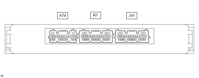
(a) Measure the voltage according to the value(s) in the table below.
| Terminal No. (Symbol) | Wiring Color | Terminal Description | Condition | Specified Condition |
|---|---|---|---|---|
| J41-10 (SWIL) - J41-11 (AGND) | W - R | Engine switch illumination drive output | Engine switch illumination on | 11 to 14 V |
| Engine switch illumination off | Below 1 V |
- If the result is not as specified, the certification ECU (smart key ECU assembly) may be malfunctioning.
CHECK MULTIPLEX NETWORK DOOR ECU
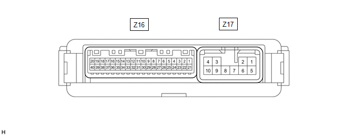
(a) Disconnect the Z16 and Z17 multiplex network door ECU connectors.
(b) Measure the voltage according to the value(s) in the table below.
HINT:
Measure the values on the wire harness side with the connector disconnected.
| Terminal No. (Symbol) | Wiring Color | Terminal Description | Condition | Specified Condition |
|---|---|---|---|---|
| Z16-20 (ECUB) - Body ground | GR - Body ground | Battery power supply | Always | 11 to 14 V |
| Z16-18 (IG) - Body ground | P - Body ground | IG power supply | Engine switch on (IG) | 11 to 14 V |
| Engine switch off | Below 1 V | |||
| Z17-1 (B) - Body ground | Y - Body ground | Battery power supply | Always | 11 to 14 V |
- If the result is not as specified, the multiplex network door ECU may be malfunctioning.
(c) Reconnect the Z16 and Z17 multiplex network door ECU connectors.
(d) Measure the voltage and check for pulses according to the value(s) in the table below.
| Terminal No. (Symbol) | Wiring Color | Terminal Description | Condition | Specified Condition |
|---|---|---|---|---|
| Z17-5 (CTYO) - Body ground | W - Body ground | Luggage compartment light drive output | Back door closed (when No. 1 luggage compartment light switch on) | 11 to 14 V |
| Back door open (when No. 1 luggage compartment light switch on) | Below 1 V | |||
| Z16-11 (FUL) - Body ground | V - Body ground | Back door lock assembly (latch courtesy switch) signal circuit | Back door closed → open | Pulse generation → Below 1 V |
 Problem Symptoms Table
PROBLEM SYMPTOMS TABLE NOTICE: Before replacing the main ECU (multiplex network body ECU), refer to Service Bulletin. HINT: Use the table below to help determine the cause of problem symptoms. If mult ...
 Diagnosis System
DIAGNOSIS SYSTEM DESCRIPTION (a) Lighting system data can be read from the Data Link Connector 3 (DLC3) of the vehicle. When the system seems to be malfunctioning, use the Techstream to check for malf ...
Other materials:
Lexus RX (RX 350L, RX450h) 2016-2026 Repair Manual > Safety Connect System: Acn Call End
ACN CALL END ACN CALL END This function terminates the ACN (Automatic Collision Notification) to the telematics provider. After a collision in which the DCM receives "Collision Detection Signal", the vehicle will send the emergency call notification to the telematics provider until the emergency cal ...
Lexus RX (RX 350L, RX450h) 2016-2026 Repair Manual > Radio Receiver: Removal
REMOVAL CAUTION / NOTICE / HINT The necessary procedures (adjustment, calibration, initialization, or registration) that must be performed after parts are removed and installed, or replaced during radio receiver assembly removal/installation are shown below. Necessary Procedures After Parts Removed/ ...
Lexus RX (RX 350L, RX450h) 2016-{YEAR} Owners Manual
- For your information
- Pictorial index
- For safety and security
- Instrument cluster
- Operation of each component
- Driving
- Lexus Display Audio system
- Interior features
- Maintenance and care
- When trouble arises
- Vehicle specifications
- For owners
Lexus RX (RX 350L, RX450h) 2016-{YEAR} Repair Manual

0.0116