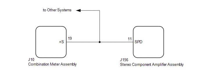
Lexus RX (RX 350L, RX450h) 2016-2026 Repair Manual: Vehicle Speed Signal Circuit between Stereo Component Amplifier and Combination Meter
DESCRIPTION
The stereo component amplifier assembly receives a vehicle speed signal from the combination meter assembly to control the ASL function.
HINT:
- A voltage of 12 V or 5 V is output from each ECU and then input to the combination meter assembly. The signal is changed to a pulse signal at the transistor in the combination meter assembly. Each ECU controls its respective systems based on this pulse signal.
- If a short occurs in any of the ECUs or in the wire harness connected to an ECU, all systems in the following diagram will not operate normally.
WIRING DIAGRAM
PROCEDURE
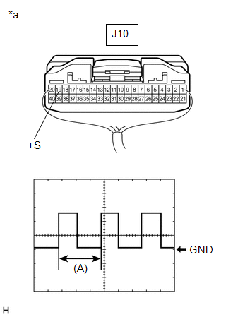
| 1. | INSPECT COMBINATION METER ASSEMBLY (OUTPUT WAVEFORM) |
| (a) Check the output waveform. (1) Remove the combination meter assembly with the connector(s) still connected. (2) Connect an oscilloscope to terminal J10-19 (+S) and body ground. (3) Turn the engine switch on (IG). (4) Turn a wheel slowly. (5) Check the signal waveform according to the condition(s) in the table below.
OK: The waveform is similar to that shown in the illustration. HINT: When the system is functioning normally, one wheel revolution generates 4 pulses. As the vehicle speed increases, the width indicated by (A) in the illustration narrows. |
|
| NG |  | GO TO METER / GAUGE SYSTEM |
|

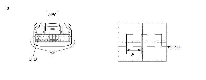
| 2. | INSPECT STEREO COMPONENT AMPLIFIER ASSEMBLY (INPUT WAVEFORM) |
(a) Check the input waveform.
| *a | Component with harness connected (Stereo Component Amplifier Assembly) | - | - |
(1) Remove the stereo component amplifier assembly with the connector(s) still connected.
(2) Connect an oscilloscope to terminal J156-11 (SPD) and body ground.
(3) Turn the engine switch on (IG).
(4) Turn a wheel slowly.
(5) Check the signal waveform according to the condition(s) in the table below.
| Item | Condition |
|---|---|
| Measurement terminal | J156-11 (SPD) - Body ground |
| Tool setting | 5 V/DIV., 20 ms./DIV. |
| Vehicle condition | Wheel being rotated |
OK:
The waveform is similar to that shown in the illustration.
HINT:
When the system is functioning normally, one wheel revolution generates 4 pulses. As the vehicle speed increases, the width indicated by (A) in the illustration narrows.
| OK | | PROCEED TO NEXT SUSPECTED AREA SHOWN IN PROBLEM SYMPTOMS TABLE |
| NG | | REPAIR OR REPLACE HARNESS OR CONNECTOR (STEREO COMPONENT AMPLIFIER ASSEMBLY - COMBINATION METER ASSEMBLY) |
 AVC-LAN Circuit
DESCRIPTION Each unit of the audio and visual system connected to the AVC-LAN (communication bus) transmits signals via AVC-LAN communication. If a short to +B or short to ground occurs in an AVC-LAN ...
 Voice Guidance Circuit between Radio Receiver and Stereo Component Amplifier
DESCRIPTION Using this circuit, the radio receiver assembly sends signals to the stereo component amplifier assembly. WIRING DIAGRAM PROCEDURE 1. CHECK HARNESS AND CONNECTOR (RADIO RECEIVER ASS ...
Other materials:
Lexus RX (RX 350L, RX450h) 2016-2026 Repair Manual > Power Mirror Control System (w/ Memory): Data List / Active Test
DATA LIST / ACTIVE TEST DATA LIST HINT: Using the Techstream to read the Data List allows the values or states of switches, sensors, actuators and other items to be read without removing any parts. This non-intrusive inspection can be very useful because intermittent conditions or signals may be dis ...
Lexus RX (RX 350L, RX450h) 2016-2026 Repair Manual > Parking Assist Monitor System: Terminals Of Ecu
TERMINALS OF ECU REAR TELEVISION CAMERA ASSEMBLY (a) Disconnect the Z11 rear television camera assembly connector. (b) Measure the voltage on the wire harness side connector according to the value(s) in the table below. Terminal No. (Symbol) Wiring Color Terminal Description Condition Sp ...
Lexus RX (RX 350L, RX450h) 2016-{YEAR} Owners Manual
- For your information
- Pictorial index
- For safety and security
- Instrument cluster
- Operation of each component
- Driving
- Lexus Display Audio system
- Interior features
- Maintenance and care
- When trouble arises
- Vehicle specifications
- For owners
Lexus RX (RX 350L, RX450h) 2016-{YEAR} Repair Manual

0.01