Lexus RX (RX 350L, RX450h) 2016-2026 Repair Manual: Voice Guidance Circuit between Radio Receiver and Stereo Component Amplifier
DESCRIPTION
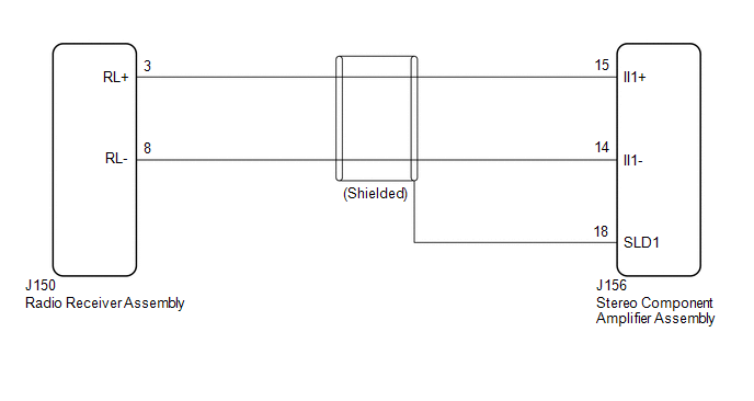
Using this circuit, the radio receiver assembly sends signals to the stereo component amplifier assembly.
WIRING DIAGRAM
PROCEDURE
| 1. | CHECK HARNESS AND CONNECTOR (RADIO RECEIVER ASSEMBLY - STEREO COMPONENT AMPLIFIER ASSEMBLY) |
(a) Disconnect the J150 radio receiver assembly connector.
(b) Disconnect the J156 stereo component amplifier assembly connector.
(c) Measure the resistance according to the value(s) in the table below.
Standard Resistance:
| Tester connection | Condition | Specified condition |
|---|---|---|
| J150-3 (RL+) - J156-15 (II1+) | Always | Below 1 Ω |
| J150-8 (RL-) - J156-14 (II1-) | Always | Below 1 Ω |
| J156-18 (SLD1) - Body ground | Always | 10 kΩ or higher |
| J150-3 (RL+) or J156-15 (II1+) - Body ground | Always | 10 kΩ or higher |
| J150-8 (RL-) or J156-14 (II1-) - Body ground | Always | 10 kΩ or higher |
| OK |  | PROCEED TO NEXT SUSPECTED AREA SHOWN IN PROBLEM SYMPTOMS TABLE |
| NG | | REPAIR OR REPLACE HARNESS OR CONNECTOR |
 Vehicle Speed Signal Circuit between Stereo Component Amplifier and Combination Meter
DESCRIPTION The stereo component amplifier assembly receives a vehicle speed signal from the combination meter assembly to control the ASL function. HINT:
A voltage of 12 V or 5 V is output from ea ...
 Microphone Circuit
DESCRIPTION
The radio receiver assembly and telephone microphone assembly are connected to each other using the microphone connection detection signal lines.
Using this circuit, the radio receive ...
Other materials:
Lexus RX (RX 350L, RX450h) 2016-2026 Repair Manual > Purge Valve: Inspection
INSPECTION PROCEDURE 1. INSPECT PURGE VALVE (PURGE VSV) (for TMMC Made) (a) Measure the resistance according to the value(s) in the table below. Standard Resistance: Tester Connection Condition Specified Condition 1 - 2 20°C (68°F) 23 to 26 Ω If the result is not as specified, ...
Lexus RX (RX 350L, RX450h) 2016-2026 Repair Manual > Dynamic Torque Control Awd System: Terminals Of Ecu
TERMINALS OF ECU CHECK 4WD ECU ASSEMBLY (a) Measure the voltage and resistance of the connector. Terminal No. (Symbol) Wiring Color Terminal Description Condition Specified Condition R10-10 (4WDS) - R10-4 (GND) P - W-B AWD lock mode switch signal Engine switch on (IG) AWD lock ...
Lexus RX (RX 350L, RX450h) 2016-{YEAR} Owners Manual
- For your information
- Pictorial index
- For safety and security
- Instrument cluster
- Operation of each component
- Driving
- Lexus Display Audio system
- Interior features
- Maintenance and care
- When trouble arises
- Vehicle specifications
- For owners
Lexus RX (RX 350L, RX450h) 2016-{YEAR} Repair Manual

0.0111