Lexus RX (RX 350L, RX450h) 2016-2026 Repair Manual: Power Seat Motor Circuit
DESCRIPTION
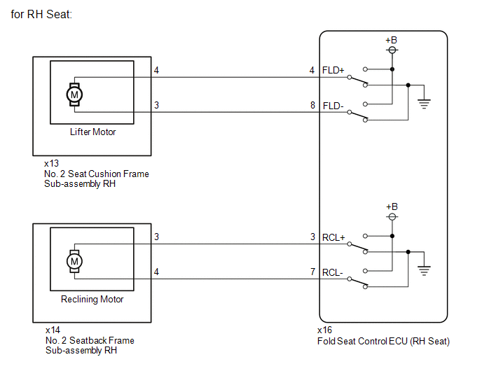
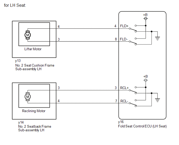
When a switch of the fold seat switch assembly or No. 1 fold seat switch assembly is pushed, the fold seat control ECU receives a switch operation signal and operates each motor.
WIRING DIAGRAM
CAUTION / NOTICE / HINT
NOTICE:
-
When a fold seat control ECU (RH/LH seat) is replaced, it is necessary to perform initialization.
Click here
.gif)
-
When No. 2 seat cushion frame sub-assembly RH, No. 2 seat cushion frame sub-assembly LH, No. 2 seatback frame sub-assembly RH or No. 2 seatback frame sub-assembly LH is removed and reinstalled, it is necessary to perform initialization.
Click here
PROCEDURE
| 1. | CHECK REAR POWER SEAT CONTROL SYSTEM (for Third Row) |
(a) Check that the rear power seat control system (for Third Row) function operates normally.
| Result | Proceed to |
|---|---|
| Lifter motor (RH) does not operate normally. | A |
| Reclining motor (RH) does not operate normally. | B |
| Lifter motor (LH) does not operate normally. | C |
| Reclining motor (LH) does not operate normally. | D |
| B | .gif) | GO TO STEP 5 |
| C | | GO TO STEP 8 |
| D | | GO TO STEP 11 |
|
.gif)
| 2. | INSPECT NO. 2 SEAT CUSHION FRAME SUB-ASSEMBLY RH (LIFTER MOTOR) |
(a) Remove the No. 2 seat cushion frame sub-assembly RH.
Click here
(b) Inspect the No. 2 seat cushion frame sub-assembly RH. (Lifter Motor)
Click here
| NG | | REPLACE NO. 2 SEAT CUSHION FRAME SUB-ASSEMBLY RH |
|
| 3. | CHECK FOLD SEAT CONTROL ECU (RH SEAT) |
(a) Measure the voltage according to the value(s) in the table below.
Standard Voltage:
| Tester Connection | Condition | Specified Condition |
|---|---|---|
| x13-4 - Body ground | Fold switch (RH) of fold seat switch assembly or No. 1 fold seat switch assembly pushed | 11 to 14 V |
| x13-3 - Body ground | Return switch (RH) of fold seat switch assembly or No. 1 fold seat switch assembly pushed | 11 to 14 V |
| OK | | PROCEED TO NEXT SUSPECTED AREA SHOWN IN PROBLEM SYMPTOMS TABLE |
|
| 4. | CHECK HARNESS AND CONNECTOR (FOLD SEAT CONTROL ECU (RH SEAT) - NO. 2 SEAT CUSHION FRAME SUB-ASSEMBLY RH) |
(a) Disconnect the x16 fold seat control ECU (RH seat) connector.
(b) Measure the resistance according to the value(s) in the table below.
Standard Resistance:
| Tester Connection | Condition | Specified Condition |
|---|---|---|
| x16-4 (FLD+) - x13-4 | Always | Below 1 Ω |
| x16-4 (FLD+) or x13-4 - Body ground | Always | 10 kΩ or higher |
| x16-8 (FLD-) - x13-3 | Always | Below 1 Ω |
| x16-8 (FLD-) or x13-3 - Body ground | Always | 10 kΩ or higher |
| OK | | REPLACE FOLD SEAT CONTROL ECU (RH SEAT) |
| NG | | REPAIR OR REPLACE HARNESS OR CONNECTOR |
| 5. | INSPECT NO. 2 SEAT BACKFRAME SUB-ASSEMBLY RH (RECLINING MOTOR) |
(a) Remove the No. 2 seatback frame sub-assembly RH.
Click here
(b) Inspect the No. 2 seatback frame sub-assembly RH. (Reclining Motor)
Click here
| NG | | REPLACE NO. 2 SEATBACK FRAME SUB-ASSEMBLY RH |
|
| 6. | CHECK FOLD SEAT CONTROL ECU (RH SEAT) |
(a) Measure the voltage according to the value(s) in the table below.
Standard Voltage:
| Tester Connection | Condition | Specified Condition |
|---|---|---|
| x14-3 - Body ground | Fold switch (RH) of fold seat switch assembly or No. 1 fold seat switch assembly pushed | 11 to 14 V |
| x14-4 - Body ground | Return switch (RH) of fold seat switch assembly or No. 1 fold seat switch assembly pushed | 11 to 14 V |
| OK | | PROCEED TO NEXT SUSPECTED AREA SHOWN IN PROBLEM SYMPTOMS TABLE |
|
| 7. | CHECK HARNESS AND CONNECTOR (FOLD SEAT CONTROL ECU (RH SEAT) - NO. 2 SEATBACK FRAME SUB-ASSEMBLY RH) |
(a) Disconnect the x16 fold seat control ECU (RH seat) connector.
(b) Measure the resistance according to the value(s) in the table below.
Standard Resistance:
| Tester Connection | Condition | Specified Condition |
|---|---|---|
| x16-3 (RCL+) - x14-3 | Always | Below 1 Ω |
| x16-3 (RCL+) or x14-3 - Body ground | Always | 10 kΩ or higher |
| x16-7 (RCL-) - x14-4 | Always | Below 1 Ω |
| x16-7 (RCL-) or x14-4 - Body ground | Always | 10 kΩ or higher |
| OK | | REPLACE FOLD SEAT CONTROL ECU (RH SEAT) |
| NG | | REPAIR OR REPLACE HARNESS OR CONNECTOR |
| 8. | INSPECT NO. 2 SEAT CUSHION FRAME SUB-ASSEMBLY LH (LIFTER MOTOR) |
(a) Remove the No. 2 seat cushion frame sub-assembly LH.
Click here
(b) Inspect the No. 2 seat cushion frame sub-assembly LH. (Lifter Motor)
Click here
| NG | | REPLACE NO. 2 SEAT CUSHION FRAME SUB-ASSEMBLY LH |
|
| 9. | CHECK FOLD SEAT CONTROL ECU (LH SEAT) |
(a) Measure the voltage according to the value(s) in the table below.
Standard Voltage:
| Tester Connection | Condition | Specified Condition |
|---|---|---|
| y13-4 - Body ground | Fold switch (LH) of fold seat switch assembly or No. 1 fold seat switch assembly pushed | 11 to 14 V |
| y13-3 - Body ground | Return switch (LH) of fold seat switch assembly or No. 1 fold seat switch assembly pushed | 11 to 14 V |
| OK | | PROCEED TO NEXT SUSPECTED AREA SHOWN IN PROBLEM SYMPTOMS TABLE |
|
| 10. | CHECK HARNESS AND CONNECTOR (FOLD SEAT CONTROL ECU (LH SEAT) - NO. 2 SEAT CUSHION FRAME SUB-ASSEMBLY LH) |
(a) Disconnect the y16 fold seat control ECU (LH seat) connector.
(b) Measure the resistance according to the value(s) in the table below.
Standard Resistance:
| Tester Connection | Condition | Specified Condition |
|---|---|---|
| y16-4 (FLD+) - y13-4 | Always | Below 1 Ω |
| y16-4 (FLD+) or y13-4 - Body ground | Always | 10 kΩ or higher |
| y16-8 (FLD-) - y13-3 | Always | Below 1 Ω |
| y16-8 (FLD-) or y13-3 - Body ground | Always | 10 kΩ or higher |
| OK | | REPLACE FOLD SEAT CONTROL ECU (LH SEAT) |
| NG | | REPAIR OR REPLACE HARNESS OR CONNECTOR |
| 11. | INSPECT NO.2 SEATBACK FRAME SUB-ASSEMBLY LH (RECLINING MOTOR) |
(a) Remove the No. 2 seatback frame sub-assembly LH.
Click here
(b) Inspect the No. 2 seatback frame sub-assembly LH. (Reclining Motor)
Click here
| NG | | REPLACE NO.2 SEATBACK FRAME SUB-ASSEMBLY LH |
|
| 12. | CHECK FOLD SEAT CONTROL ECU (LH SEAT) |
(a) Measure the voltage according to the value(s) in the table below.
Standard Voltage:
| Tester Connection | Condition | Specified Condition |
|---|---|---|
| y14-3 - Body ground | Fold switch (LH) of fold seat switch assembly or No. 1 fold seat switch assembly pushed | 11 to 14 V |
| y14-4 - Body ground | Return switch (LH) of fold seat switch assembly or No. 1 fold seat switch assembly pushed | 11 to 14 V |
| OK | | PROCEED TO NEXT SUSPECTED AREA SHOWN IN PROBLEM SYMPTOMS TABLE |
|
| 13. | CHECK HARNESS AND CONNECTOR (FOLD SEAT CONTROL ECU (LH SEAT) - NO. 2 SEATBACK FRAME SUB-ASSEMBLY LH) |
(a) Disconnect the y16 fold seat control ECU (LH seat) connector.
(b) Measure the resistance according to the value(s) in the table below.
Standard Resistance:
| Tester Connection | Condition | Specified Condition |
|---|---|---|
| y16-3 (RCL+) - y14-3 | Always | Below 1 Ω |
| y16-3 (RCL+) or y14-3 - Body ground | Always | 10 kΩ or higher |
| y16-7 (RCL-) - y14-4 | Always | Below 1 Ω |
| y16-7 (RCL-) or y14-4 - Body ground | Always | 10 kΩ or higher |
| OK | | REPLACE FOLD SEAT CONTROL ECU (LH SEAT) |
| NG | | REPAIR OR REPLACE HARNESS OR CONNECTOR |
 Position Sensor Circuit
DESCRIPTION When a fold seat control ECU receives signals from the fold seat switch assembly or No. 1 fold seat switch assembly, it operates the reclining motor and lifter motor of its corresponding r ...
 Power Source Circuit
DESCRIPTION Power is supplied to each fold seat control ECU through fuses. WIRING DIAGRAM CAUTION / NOTICE / HINT NOTICE: Inspect the fuses for circuits related to this system before performing the f ...
Other materials:
Lexus RX (RX 350L, RX450h) 2016-2026 Repair Manual > Headup Display System: Dtc Check / Clear
DTC CHECK / CLEAR CHECK DTC (a) Connect the Techstream to the DLC3. (b) Turn the engine switch on (IG). (c) Turn the Techstream on. (d) Enter the following menus: Body Electrical / Head Up Display / Trouble Codes. (e) Check for DTCs. Body Electrical > Head Up Display > Trouble Codes CLEAR DTC ...
Lexus RX (RX 350L, RX450h) 2016-2026 Repair Manual > Vehicle Stability Control System: Left Rear Wheel Speed Sensor Signal Has Too Many Pulses (C050C3A,C05123A)
DESCRIPTION Refer to DTC C050C1F. Click here DTC No. Detection Item DTC Detection Condition Trouble Area C050C3A Left Rear Wheel Speed Sensor Signal Has Too Many Pulses When not in Dealer Mode (Signal Check) or Inspection Mode, the output of the speed sensor detected by the skid c ...
Lexus RX (RX 350L, RX450h) 2016-{YEAR} Owners Manual
- For your information
- Pictorial index
- For safety and security
- Instrument cluster
- Operation of each component
- Driving
- Lexus Display Audio system
- Interior features
- Maintenance and care
- When trouble arises
- Vehicle specifications
- For owners
Lexus RX (RX 350L, RX450h) 2016-{YEAR} Repair Manual

0.0111