Lexus RX (RX 350L, RX450h) 2016-2026 Repair Manual: Power Source Circuit
DESCRIPTION
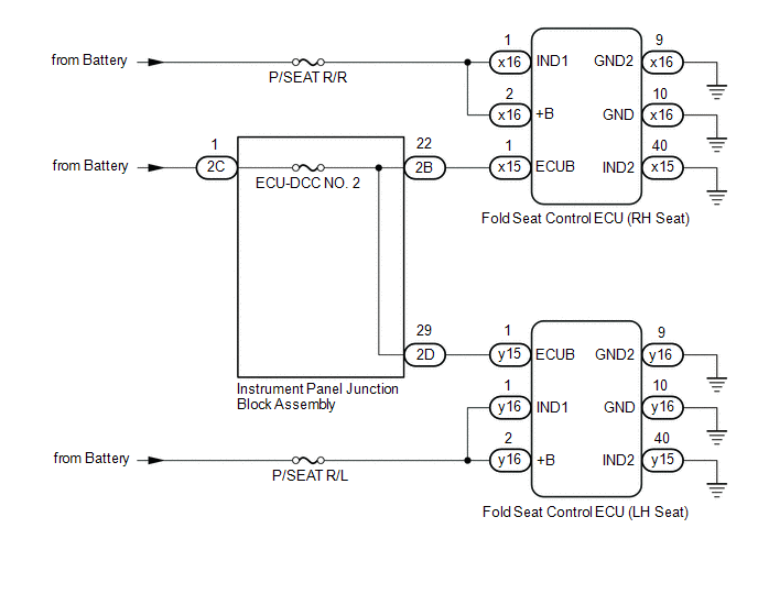
Power is supplied to each fold seat control ECU through fuses.
WIRING DIAGRAM
CAUTION / NOTICE / HINT
NOTICE:
Inspect the fuses for circuits related to this system before performing the following procedure.
PROCEDURE
| 1. | CHECK REAR POWER SEAT CONTROL SYSTEM (for Third Row) |
(a) Check that the rear power seat control system (for Third Row) function operates normally.
| Result | Proceed to |
|---|---|
| Fold/Return functions of both rear No .2 power seats do not operate normally. | A |
| Fold/Return functions of rear No. 2 power seat RH do not operate normally. | B |
| Fold/Return functions of rear No. 2 power seat LH do not operate normally. | C |
| B | .gif) | GO TO STEP 5 |
| C | | GO TO STEP 8 |
|
.gif)
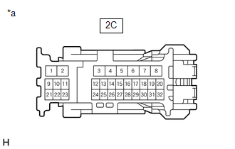
| 2. | CHECK HARNESS AND CONNECTOR (BATTERY POWER SUPPLY) |
| (a) Disconnect the 2C instrument panel junction block assembly connector |
|
(b) Measure the voltage according to the value(s) in the table below.
Standard Voltage:
| Tester Connection | Condition | Specified Condition |
|---|---|---|
| 2C-1 - Body ground | Always | 11 to 14 V |
| NG | | REPAIR OR REPLACE HARNESS OR CONNECTOR |
|
| 3. | CHECK HARNESS AND CONNECTOR (BATTERY POWER SUPPLY) |
| (a) Disconnect the x15 fold seat control ECU (RH seat) connector. |
|
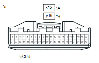
(b) Disconnect the y15 fold seat control ECU (LH seat) connector.
(c) Measure the voltage according to the value(s) in the table below.
Standard Voltage:
| Tester Connection | Condition | Specified Condition |
|---|---|---|
| x15-1 (ECUB) - Body ground | Always | 11 to 14 V |
| y15-1 (ECUB) - Body ground | Always | 11 to 14 V |
| OK | | PROCEED TO NEXT SUSPECTED AREA SHOWN IN PROBLEM SYMPTOMS TABLE |
|
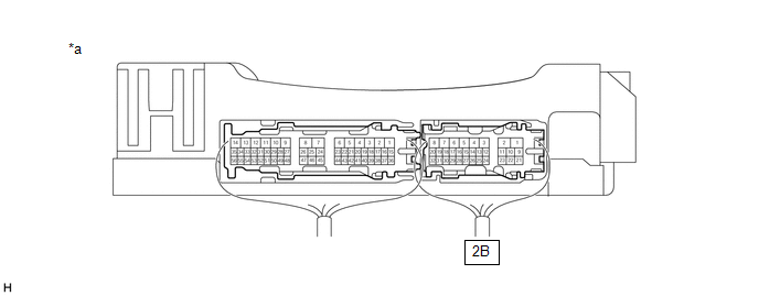
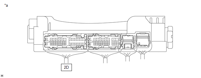
| 4. | CHECK HARNESS AND CONNECTOR (INSTRUMENT PANEL JUNCTION BLOCK ASSEMBLY - FOLD SEAT CONTROL ECU (RH/LH SEAT)) |
(a) Disconnect the 2B and 2D instrument panel junction block assembly connector
(b) Measure the resistance according to the value(s) in the table below.
Standard Resistance:
| Tester Connection | Condition | Specified Condition |
|---|---|---|
| 2B-22 or x15-1 (ECUB) - Body ground | Always | 10 kΩ or higher |
| 2D-29 or y15-1 (ECUB) - Body ground | Always | 10 kΩ or higher |
| OK | | REPLACE INSTRUMENT PANEL JUNCTION BLOCK ASSEMBLY |
.gif)
| NG | | REPAIR OR REPLACE HARNESS OR CONNECTOR |
| 5. | INSPECT INSTRUMENT PANEL JUNCTION BLOCK ASSEMBLY |
(a) Measure the voltage according to the value(s) in the table below.
| *a | Component with harness connected (Instrument Panel Junction Block Assembly) | - | - |
Standard Voltage:
| Tester Connection | Condition | Specified Condition |
|---|---|---|
| 2B-22 - Body ground | Always | 11 to 14 V |
| NG | | REPLACE INSTRUMENT PANEL JUNCTION BLOCK ASSEMBLY |
|
| 6. | CHECK HARNESS AND CONNECTOR (INSTRUMENT PANEL JUNCTION BLOCK ASSEMBLY - FOLD SEAT CONTROL ECU (RH SEAT)) |
(a) Disconnect the x15 fold seat control ECU (RH seat) connector.
(b) Measure the resistance according to the value(s) in the table below.
Standard Resistance:
| Tester Connection | Condition | Specified Condition |
|---|---|---|
| 2B-22 - x15-1 (ECUB) | Always | Below 1 Ω |
| NG | | REPAIR OR REPLACE HARNESS OR CONNECTOR |
|
| 7. | CHECK HARNESS AND CONNECTOR (FOLD SEAT CONTROL ECU (RH SEAT) - BATTERY POWER SUPPLY AND BODY GROUND) |
| (a) Disconnect the x16 fold seat control ECU (RH seat) connector. |
|

(b) Measure the voltage and resistance according to the value(s) in the table below.
Standard Voltage:
| Tester Connection | Condition | Specified Condition |
|---|---|---|
| x16-1 (IND1) - Body ground | Always | 11 to 14 V |
| x16-2 (+B) - Body ground | Always | 11 to 14 V |
(c) Measure the resistance according to the value(s) in the table below.
Standard Resistance:
| Tester Connection | Condition | Specified Condition |
|---|---|---|
| x15-40 (IND2) - Body ground | Always | Below 1 Ω |
| x16-9 (GND2) - Body ground | Always | Below 1 Ω |
| x16-10 (GND) - Body ground | Always | Below 1 Ω |
| OK | | PROCEED TO NEXT SUSPECTED AREA SHOWN IN PROBLEM SYMPTOMS TABLE |
| NG | | REPAIR OR REPLACE HARNESS OR CONNECTOR |
| 8. | INSPECT INSTRUMENT PANEL JUNCTION BLOCK ASSEMBLY |
(a) Measure the voltage according to the value(s) in the table below
| *a | Component with harness connected (Instrument Panel Junction Block Assembly) | - | - |
Standard Voltage:
| Tester Connection | Condition | Specified Condition |
|---|---|---|
| 2D-29 - Body ground | Always | 11 to 14 V |
| NG | | REPLACE INSTRUMENT PANEL JUNCTION BLOCK ASSEMBLY |
|
| 9. | CHECK HARNESS AND CONNECTOR (INSTRUMENT PANEL JUNCTION BLOCK ASSEMBLY - FOLD SEAT CONTROL ECU (LH SEAT)) |
(a) Disconnect the y15 fold seat control ECU (LH seat) connector.
(b) Measure the resistance according to the value(s) in the table below.
Standard Resistance:
| Tester Connection | Condition | Specified Condition |
|---|---|---|
| y15-1 (ECUB) - 2D-29 | Always | Below 1 Ω |
| NG | | REPAIR OR REPLACE HARNESS OR CONNECTOR |
|
| 10. | CHECK HARNESS AND CONNECTOR (FOLD SEAT CONTROL ECU (LH SEAT) - BATTERY POWER SUPPLY AND BODY GROUND) |
| (a) Disconnect the y16 fold seat control ECU (LH seat) connector. |
|
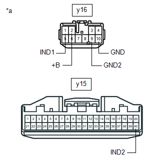
(b) Measure the voltage according to the value(s) in the table below.
Standard Voltage:
| Tester Connection | Condition | Specified Condition |
|---|---|---|
| y16-1 (IND1) - Body ground | Always | 11 to 14 V |
| y16-2 (+B) - Body ground | Always | 11 to 14 V |
(c) Measure the resistance according to the value(s) in the table below.
Standard Resistance:
| Tester Connection | Condition | Specified Condition |
|---|---|---|
| y15-40 (IND2) - Body ground | Always | Below 1 Ω |
| y16-9 (GND2) - Body ground | Always | Below 1 Ω |
| y16-10 (GND) - Body ground | Always | Below 1 Ω |
| OK | | PROCEED TO NEXT SUSPECTED AREA SHOWN IN PROBLEM SYMPTOMS TABLE |
| NG | | REPAIR OR REPLACE HARNESS OR CONNECTOR |
 Power Seat Motor Circuit
DESCRIPTION When a switch of the fold seat switch assembly or No. 1 fold seat switch assembly is pushed, the fold seat control ECU receives a switch operation signal and operates each motor. WIRING DI ...

Other materials:
Lexus RX (RX 350L, RX450h) 2016-2026 Repair Manual > Door Courtesy Light: Removal
REMOVAL PROCEDURE 1. REMOVE COURTESY LIGHT ASSEMBLY (for Front Door) (a) Using a screwdriver with its tip wrapped with protective tape, disengage the claw. *A for LH Side *B for RH Side *a Protective Tape (b) Disconnect the connector to remove the courtesy ligh ...
Lexus RX (RX 350L, RX450h) 2016-2026 Repair Manual > Steering Pad Switch: Inspection
INSPECTION PROCEDURE 1. INSPECT STEERING PAD SWITCH ASSEMBLY (a) Measure the resistance according to the value(s) in the table below. Text in Illustration *A w/ Lane Departure Alert System - - *a Component without harness connected (Steering Pad Switch Assembly) *b Seek+ *c ...
Lexus RX (RX 350L, RX450h) 2016-{YEAR} Owners Manual
- For your information
- Pictorial index
- For safety and security
- Instrument cluster
- Operation of each component
- Driving
- Lexus Display Audio system
- Interior features
- Maintenance and care
- When trouble arises
- Vehicle specifications
- For owners
Lexus RX (RX 350L, RX450h) 2016-{YEAR} Repair Manual

0.0123