Lexus RX (RX 350L, RX450h) 2016-2026 Repair Manual: Position Sensor Circuit
DESCRIPTION
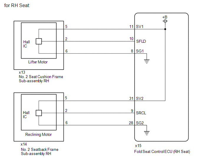
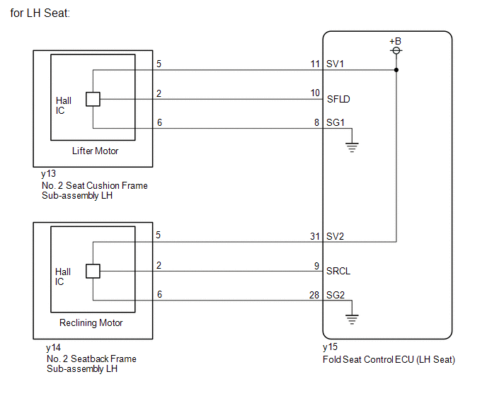
When a fold seat control ECU receives signals from the fold seat switch assembly or No. 1 fold seat switch assembly, it operates the reclining motor and lifter motor of its corresponding rear No. 2 power seat. When the reclining motor or lifter motor is operating, the position sensor (Hall IC) in it outputs signals. These signals are received by the corresponding fold seat control ECU, which uses them to detect the position of the seatback and seat cushion.
WIRING DIAGRAM
CAUTION / NOTICE / HINT
NOTICE:
-
When a fold seat control ECU (RH/LH seat) is replaced, it is necessary to perform initialization.
Click here
.gif)
-
When No. 2 seat cushion frame sub-assembly RH, No. 2 seat cushion frame sub-assembly LH, No. 2 seatback frame sub-assembly RH or No. 2 seatback frame sub-assembly LH is removed and reinstalled, it is necessary to perform initialization.
Click here
PROCEDURE
| 1. | CHECK REAR POWER SEAT CONTROL SYSTEM (for Third Row) |
(a) Check that the rear power seat control system (for Third Row) function operates normally.
| Result | Proceed to |
|---|---|
| Fold/Return functions of rear No. 2 power seat RH do not operate normally. | A |
| Fold/Return functions of rear No. 2 power seat LH do not operate normally. | B |
| B | .gif) | GO TO STEP 8 |
|
.gif)
| 2. | CHECK FOLD SEAT CONTROL ECU (RH SEAT) (SENSOR POWER SOURCE) |
(a) Disconnect the x13 No. 2 seat cushion frame sub-assembly RH connector.
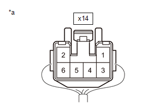
(b) Disconnect the x14 No. 2 seatback frame sub-assembly RH connector.
(c) Measure the voltage according to the value(s) in the table below.
Standard Voltage:
Lifter Motor| Tester Connection | Condition | Specified Condition |
|---|---|---|
| x13-5 - x13-6 | Fold switch (RH) of fold seat switch assembly or No. 1 fold seat switch assembly pushed | 5.5 to 10 V |
| Tester Connection | Condition | Specified Condition |
|---|---|---|
| x14-5 - x14-6 | Return switch (RH) of fold seat switch assembly or No. 1 fold seat switch assembly pushed | 5.5 to 10 V |
| NG | | GO TO STEP 5 |
|
| 3. | CHECK NO. 2 SEAT CUSHION FRAME SUB-ASSEMBLY RH (SENSOR SIGNAL) |
| (a) Reconnect the x13 No. 2 seat cushion frame sub-assembly RH connector. |
|

(b) Using an oscilloscope, check the waveform.
OK:
| Tester Connection | Condition | Specified Condition |
|---|---|---|
| x13-2 - Body ground | Lifter motor operating | Pulse generation (Hi: 5.5 to 10 V, Lo: Below 1 V) |
| NG | | GO TO STEP 6 |
|
| 4. | CHECK NO. 2 SEATBACK FRAME SUB-ASSEMBLY RH (SENSOR SIGNAL) |
| (a) Reconnect the x14 No. 2 seatback frame sub-assembly RH connector. |
|
(b) Using an oscilloscope, check the waveform.
OK:
| Tester Connection | Condition | Specified Condition |
|---|---|---|
| x14-2 - Body ground | Reclining motor operation | Pulse generation (Hi: 5.5 to 10 V, Lo: Below 1 V) |
| OK | | PROCEED TO NEXT SUSPECTED AREA SHOWN IN PROBLEM SYMPTOMS TABLE |
| NG | | GO TO STEP 7 |
| 5. | CHECK HARNESS AND CONNECTOR (NO. 2 SEAT CUSHION FRAME SUB-ASSEMBLY RH AND NO. 2 SEATBACK FRAME SUB-ASSEMBLY RH - FOLD SEAT CONTROL ECU (RH SEAT)) |
(a) Disconnect the x15 fold seat control ECU (RH seat) connector.
(b) Measure the resistance according to the value(s) in the table below.
Standard Resistance:
Lifter Motor| Tester Connection | Condition | Specified Condition |
|---|---|---|
| x13-5 - x15-11 (SV1) | Always | Below 1 Ω |
| x13-5 or x15-11 (SV1) - Body ground | Always | 10 kΩ or higher |
| x13-6 - x15-8 (SG1) | Always | Below 1 Ω |
| x13-6 or x15-8 (SG1) - Body ground | Always | 10 kΩ or higher |
| Tester Connection | Condition | Specified Condition |
|---|---|---|
| x14-5 - x15-31 (SV2) | Always | Below 1 Ω |
| x14-5 or x15-31 (SV2) - Body ground | Always | 10 kΩ or higher |
| x14-6 - x15-28 (SG2) | Always | Below 1 Ω |
| x14-6 or x15-28 (SG2) - Body ground | Always | 10 kΩ or higher |
| OK | | REPLACE FOLD SEAT CONTROL ECU (RH SEAT) |
| NG | | REPAIR OR REPLACE HARNESS OR CONNECTOR |
| 6. | CHECK HARNESS AND CONNECTOR (NO. 2 SEAT CUSHION FRAME SUB-ASSEMBLY RH - FOLD SEAT CONTROL ECU (RH SEAT)) |
(a) Disconnect the x15 fold seat control ECU (RH seat) connector.
(b) Measure the resistance according to the value(s) in the table below.
Standard Resistance:
| Tester Connection | Condition | Specified Condition |
|---|---|---|
| x13-2 - x15-10 (SFLD) | Always | Below 1 Ω |
| x13-2 or x15-10 (SFLD) - Body ground | Always | 10 kΩ or higher |
| OK | | REPLACE FOLD SEAT CONTROL ECU (RH SEAT) |
| NG | | REPAIR OR REPLACE HARNESS OR CONNECTOR |
| 7. | CHECK HARNESS AND CONNECTOR (NO. 2 SEATBACK FRAME SUB-ASSEMBLY RH - FOLD SEAT CONTROL ECU (RH SEAT)) |
(a) Disconnect the x15 fold seat control ECU (RH seat) connector.
(b) Measure the resistance according to the value(s) in the table below.
Standard Resistance:
| Tester Connection | Condition | Specified Condition |
|---|---|---|
| x14-2 - x15-9 (SRCL) | Always | Below 1 Ω |
| x14-2 or x15-9 (SRCL) - Body ground | Always | 10 kΩ or higher |
| OK | | REPLACE FOLD SEAT CONTROL ECU (RH SEAT) |
| NG | | REPAIR OR REPLACE HARNESS OR CONNECTOR |
| 8. | CHECK FOLD SEAT CONTROL ECU (LH SEAT) (SENSOR POWER SOURCE) |
(a) Disconnect the y13 No. 2 seat cushion frame sub-assembly LH connector.
(b) Disconnect the y14 No. 2 seatback frame sub-assembly LH connector.
(c) Measure the voltage according to the value(s) in the table below.
Standard Voltage:
Lifter Motor| Tester Connection | Condition | Specified Condition |
|---|---|---|
| y13-5 - y13-6 | Fold switch (LH) of fold seat switch assembly or No. 1 fold seat switch assembly pushed | 5.5 to 10 V |
| Tester Connection | Condition | Specified Condition |
|---|---|---|
| y14-5 - y14-6 | Return switch (LH) of fold seat switch assembly or No. 1 fold seat switch assembly pushed | 5.5 to 10 V |
| NG | | GO TO STEP 11 |
|
| 9. | CHECK NO. 2 SEAT CUSHION FRAME SUB-ASSEMBLY LH (SENSOR SIGNAL) |
| (a) Reconnect the y13 No. 2 seat cushion frame sub-assembly LH connector. |
|

(b) Using an oscilloscope, check the waveform.
OK:
| Tester Connection | Condition | Specified Condition |
|---|---|---|
| y13-2 - Body ground | Lifter motor operation | Pulse generation (Hi: 5.5 to 10 V, Lo: Below 1 V) |
| NG | | GO TO STEP 12 |
|
| 10. | CHECK NO. 2 SEATBACK FRAME SUB-ASSEMBLY LH (SENSOR SIGNAL) |
| (a) Reconnect the y14 No. 2 seatback frame sub-assembly LH connector. |
|

(b) Using an oscilloscope, check the waveform.
OK:
| Tester Connection | Condition | Specified Condition |
|---|---|---|
| y14-2 - Body ground | Reclining motor operation | Pulse generation (Hi: 5.5 to 10 V, Lo: Below 1 V) |
| OK | | PROCEED TO NEXT SUSPECTED AREA SHOWN IN PROBLEM SYMPTOMS TABLE |
| NG | | GO TO STEP 13 |
| 11. | CHECK HARNESS AND CONNECTOR (NO. 2 SEAT CUSHION FRAME SUB-ASSEMBLY LH AND NO. 2 SEATBACK FRAME SUB-ASSEMBLY LH - FOLD SEAT CONTROL ECU (LH SEAT)) |
(a) Disconnect the y15 fold seat control ECU (LH seat) connector.
(b) Measure the resistance according to the value(s) in the table below.
Standard Resistance:
Lifter Motor| Tester Connection | Condition | Specified Condition |
|---|---|---|
| y13-5 - y15-11 (SV1) | Always | Below 1 Ω |
| y13-5 or y15-11 (SV1) - Body ground | Always | 10 kΩ or higher |
| y13-6 - y15-8 (SG1) | Always | Below 1 Ω |
| y13-6 or y15-8 (SG1) - Body ground | Always | 10 kΩ or higher |
| Tester Connection | Condition | Specified Condition |
|---|---|---|
| y14-5 - y15-31 (SV2) | Always | Below 1 Ω |
| y14-5 or y15-31 (SV2) - Body ground | Always | 10 kΩ or higher |
| y14-6 - y15-28 (SG2) | Always | Below 1 Ω |
| y14-6 or y15-28 (SG2) - Body ground | Always | 10 kΩ or higher |
| OK | | REPLACE FOLD SEAT CONTROL ECU (LH SEAT) |
| NG | | REPAIR OR REPLACE HARNESS OR CONNECTOR |
| 12. | CHECK HARNESS AND CONNECTOR (NO. 2 SEAT CUSHION FRAME SUB-ASSEMBLY LH - FOLD SEAT CONTROL ECU (LH SEAT)) |
(a) Disconnect the y15 fold seat control ECU (LH seat) connector.
(b) Measure the resistance according to the value(s) in the table below.
Standard Resistance:
| Tester Connection | Condition | Specified Condition |
|---|---|---|
| y13-2 - y15-10 (SFLD) | Always | Below 1 Ω |
| y13-2 or y15-10 (SFLD) - Body ground | Always | 10 kΩ or higher |
| OK | | REPLACE FOLD SEAT CONTROL ECU (LH SEAT) |
| NG | | REPAIR OR REPLACE HARNESS OR CONNECTOR |
| 13. | CHECK HARNESS AND CONNECTOR (NO. 2 SEATBACK FRAME SUB-ASSEMBLY LH - FOLD SEAT CONTROL ECU (LH SEAT)) |
(a) Disconnect the y15 fold seat control ECU (LH seat) connector.
(b) Measure the resistance according to the value(s) in the table below.
Standard Resistance:
| Tester Connection | Condition | Specified Condition |
|---|---|---|
| y14-2 - y15-9 (SRCL) | Always | Below 1 Ω |
| y14-2 or y15-9 (SRCL) - Body ground | Always | 10 kΩ or higher |
| OK | | REPLACE FOLD SEAT CONTROL ECU (LH SEAT) |
| NG | | REPAIR OR REPLACE HARNESS OR CONNECTOR |
 Fold Seat Switch Circuit
DESCRIPTION When a switch of the fold seat switch assembly or No. 1 fold seat switch assembly is pushed, the fold seat control ECU receives a switch operation signal and operates the fold or return fu ...
 Power Seat Motor Circuit
DESCRIPTION When a switch of the fold seat switch assembly or No. 1 fold seat switch assembly is pushed, the fold seat control ECU receives a switch operation signal and operates each motor. WIRING DI ...
Other materials:
Lexus RX (RX 350L, RX450h) 2016-2026 Repair Manual > Rear Drive Shaft Assembly: Disassembly
DISASSEMBLY PROCEDURE 1. SEPARATE REAR NO. 2 DRIVE SHAFT INBOARD JOINT BOOT CLAMP (a) Secure the drive shaft in a vise between aluminum plates. NOTICE: Do not overtighten the vise. (b) Using needle-nose pliers, disengage the 2 claws as shown in the illustration and separate the rear No. 2 drive s ...
Lexus RX (RX 350L, RX450h) 2016-2026 Repair Manual > Power Tilt And Power Telescopic Steering Column System: Tilt and Telescopic Manual Switch Circuit Malfunction (B2603)
DESCRIPTION Different voltage values are sent to the multiplex tilt and telescopic ECU by operating the tilt and telescopic switch. The multiplex tilt and telescopic ECU then judges which motor and in which direction that motor should operate based on the voltage value. DTC No. Detection Item ...
Lexus RX (RX 350L, RX450h) 2016-{YEAR} Owners Manual
- For your information
- Pictorial index
- For safety and security
- Instrument cluster
- Operation of each component
- Driving
- Lexus Display Audio system
- Interior features
- Maintenance and care
- When trouble arises
- Vehicle specifications
- For owners
Lexus RX (RX 350L, RX450h) 2016-{YEAR} Repair Manual

0.0109