Lexus RX (RX 350L, RX450h) 2016-2026 Repair Manual: Fold Seat Switch Circuit
DESCRIPTION
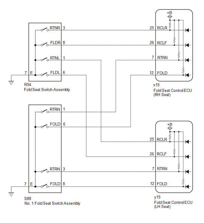
When a switch of the fold seat switch assembly or No. 1 fold seat switch assembly is pushed, the fold seat control ECU receives a switch operation signal and operates the fold or return function.
WIRING DIAGRAM
CAUTION / NOTICE / HINT
NOTICE:
When a fold seat control ECU (RH/LH seat) is replaced, it is necessary to perform initialization.
Click here .gif)
PROCEDURE
| 1. | CHECK REAR POWER SEAT CONTROL SYSTEM (for Third Row) |
(a) Check that the rear power seat control system (for Third Row) function operates normally.
| Result | Proceed to | |
|---|---|---|
| When fold seat switch assembly operated | Fold/Return functions of both rear No.2 power seats do not operate normally. | A |
| Fold function of rear No. 2 power seat RH does not operate normally. | B | |
| Return function of rear No. 2 power seat RH does not operate normally. | C | |
| Fold function of rear No. 2 power seat LH does not operate normally. | D | |
| Return function of rear No. 2 power seat LH does not operate normally. | E | |
| When No. 1 fold seat switch assembly operated | Fold/Return functions of both rear No.2 power seats do not operate normally. | F |
| Fold function of rear No. 2 power seat RH does not operate normally. | G | |
| Return function of rear No. 2 power seat RH does not operate normally. | H | |
| Fold function of rear No. 2 power seat LH does not operate normally. | I | |
| Return function of rear No. 2 power seat LH does not operate normally. | J | |
| B | .gif) | GO TO STEP 4 |
| C | | GO TO STEP 7 |
| D | | GO TO STEP 10 |
| E | | GO TO STEP 13 |
| F | | GO TO STEP 16 |
| G | | GO TO STEP 18 |
| H | | GO TO STEP 21 |
| I | | GO TO STEP 24 |
| J | | GO TO STEP 27 |
|
.gif)
| 2. | INSPECT FOLD SEAT SWITCH ASSEMBLY (GROUND) |
(a) Remove the fold seat switch assembly.
Click here
(b) Inspect the fold seat switch assembly. (Ground)
Click here
| NG | | REPLACE FOLD SEAT SWITCH ASSEMBLY |
|
| 3. | CHECK HARNESS AND CONNECTOR (FOLD SEAT SWITCH ASSEMBLY - BODY GROUND) |
(a) Measure the resistance according to the value(s) in the table below.
Standard Resistance:
| Tester Connection | Condition | Specified Condition |
|---|---|---|
| R54-7 (E) - Body ground | Always | Below 1 Ω |
| OK | | PROCEED TO NEXT SUSPECTED AREA SHOWN IN PROBLEM SYMPTOMS TABLE |
| NG | | REPAIR OR REPLACE HARNESS OR CONNECTOR |
| 4. | INSPECT FOLD SEAT SWITCH ASSEMBLY (FOLD SWITCH (RH)) |
(a) Remove the fold seat switch assembly.
Click here
(b) Inspect the fold seat switch assembly. (Fold Switch (RH))
Click here
| NG | | REPLACE FOLD SEAT SWITCH ASSEMBLY |
|
| 5. | CHECK FOLD SEAT CONTROL ECU (RH SEAT) |
(a) Measure the voltage according to the value(s) in the table below.
Standard Voltage:
| Tester Connection | Condition | Specified Condition |
|---|---|---|
| R54-8 (FLDR) - Body ground | Always | 11 to 14 V |
| OK | | PROCEED TO NEXT SUSPECTED AREA SHOWN IN PROBLEM SYMPTOMS TABLE |
|
| 6. | CHECK HARNESS AND CONNECTOR (FOLD SEAT CONTROL ECU (RH SEAT) - FOLD SEAT SWITCH ASSEMBLY) |
(a) Disconnect the x15 fold seat control ECU (RH seat) connector.
(b) Measure the resistance according to the value(s) in the table below.
Standard Resistance:
| Tester Connection | Condition | Specified Condition |
|---|---|---|
| x15-26 (RCLF) - R54-8 (FLDR) | Always | Below 1 Ω |
| x15-26 (RCLF) or R54-8 (FLDR) - Body ground | Always | 10 kΩ or higher |
| OK | | REPLACE FOLD SEAT CONTROL ECU (RH SEAT) |
| NG | | REPAIR OR REPLACE HARNESS OR CONNECTOR |
| 7. | INSPECT FOLD SEAT SWITCH ASSEMBLY (RETURN SWITCH (RH)) |
(a) Remove the fold seat switch assembly.
Click here
(b) Inspect the fold seat switch assembly. (Return Switch (RH))
Click here
| NG | | REPLACE FOLD SEAT SWITCH ASSEMBLY |
|
| 8. | CHECK FOLD SEAT CONTROL ECU (RH SEAT) |
(a) Measure the voltage according to the value(s) in the table below.
Standard Voltage:
| Tester Connection | Condition | Specified Condition |
|---|---|---|
| R54-3 (RTNR) - Body ground | Always | 11 to 14 V |
| OK | | PROCEED TO NEXT SUSPECTED AREA SHOWN IN PROBLEM SYMPTOMS TABLE |
|
| 9. | CHECK HARNESS AND CONNECTOR (FOLD SEAT CONTROL ECU (RH SEAT) - FOLD SEAT SWITCH ASSEMBLY) |
(a) Disconnect the x15 fold seat control ECU (RH seat) connector.
(b) Measure the resistance according to the value(s) in the table below.
Standard Resistance:
| Tester Connection | Condition | Specified Condition |
|---|---|---|
| x15-25 (RCLR) - R54-3 (RTNR) | Always | Below 1 Ω |
| x15-25 (RCLR) or R54-3 (RTNR) - Body ground | Always | 10 kΩ or higher |
| OK | | REPLACE FOLD SEAT CONTROL ECU (RH SEAT) |
| NG | | REPAIR OR REPLACE HARNESS OR CONNECTOR |
| 10. | INSPECT FOLD SEAT SWITCH ASSEMBLY (FOLD SWITCH (LH)) |
(a) Remove the fold seat switch assembly.
Click here
(b) Inspect the fold seat switch assembly. (Fold Switch (LH))
Click here
| NG | | REPLACE FOLD SEAT SWITCH ASSEMBLY |
|
| 11. | CHECK FOLD SEAT CONTROL ECU (LH SEAT) |
(a) Measure the voltage according to the value(s) in the table below.
Standard Voltage:
| Tester Connection | Condition | Specified Condition |
|---|---|---|
| R54-6 (FLDL) - Body ground | Always | 11 to 14 V |
| OK | | PROCEED TO NEXT SUSPECTED AREA SHOWN IN PROBLEM SYMPTOMS TABLE |
|
| 12. | CHECK HARNESS AND CONNECTOR (FOLD SEAT CONTROL ECU (LH SEAT) - FOLD SEAT SWITCH ASSEMBLY) |
(a) Disconnect the y15 fold seat control ECU (LH seat) connector.
(b) Measure the resistance according to the value(s) in the table below.
Standard Resistance:
| Tester Connection | Condition | Specified Condition |
|---|---|---|
| y15-26 (RCLF) - R54-6 (FLDL) | Always | Below 1 Ω |
| y15-26 (RCLF) or R54-6 (FLDL) - Body ground | Always | 10 kΩ or higher |
| OK | | REPLACE FOLD SEAT CONTROL ECU (LH SEAT) |
| NG | | REPAIR OR REPLACE HARNESS OR CONNECTOR |
| 13. | INSPECT FOLD SEAT SWITCH ASSEMBLY (RETURN SWITCH (LH)) |
(a) Remove the fold seat switch assembly.
Click here
(b) Inspect the fold seat switch assembly. (Return Switch (LH))
Click here
| NG | | REPLACE FOLD SEAT SWITCH ASSEMBLY |
|
| 14. | CHECK FOLD SEAT CONTROL ECU (LH SEAT) |
(a) Measure the voltage according to the value(s) in the table below.
Standard Voltage:
| Tester Connection | Condition | Specified Condition |
|---|---|---|
| R54-1 (RTNL) - Body ground | Always | 11 to 14 V |
| OK | | PROCEED TO NEXT SUSPECTED AREA SHOWN IN PROBLEM SYMPTOMS TABLE |
|
| 15. | CHECK HARNESS AND CONNECTOR (FOLD SEAT CONTROL ECU (LH SEAT) - FOLD SEAT SWITCH ASSEMBLY) |
(a) Disconnect the y15 fold seat control ECU (LH seat) connector.
(b) Measure the resistance according to the value(s) in the table below.
Standard Resistance:
| Tester Connection | Condition | Specified Condition |
|---|---|---|
| y15-25 (RCLR) - R54-1 (RTNL) | Always | Below 1 Ω |
| y15-25 (RCLR) or R54-1 (RTNL) - Body ground | Always | 10 kΩ or higher |
| OK | | REPLACE FOLD SEAT CONTROL ECU (LH SEAT) |
| NG | | REPAIR OR REPLACE HARNESS OR CONNECTOR |
| 16. | INSPECT NO. 1 FOLD SEAT SWITCH ASSEMBLY (GROUND) |
(a) Remove the No. 1 fold seat switch assembly.
Click here
(b) Inspect the No. 1 fold seat switch assembly. (Ground)
Click here
| NG | | REPLACE NO. 1 FOLD SEAT SWITCH ASSEMBLY |
|
| 17. | CHECK HARNESS AND CONNECTOR (NO. 1 FOLD SEAT SWITCH ASSEMBLY - BODY GROUND) |
(a) Measure the resistance according to the value(s) in the table below.
Standard Resistance:
| Tester Connection | Condition | Specified Condition |
|---|---|---|
| S88-7 (E) - Body ground | Always | Below 1 Ω |
| OK | | PROCEED TO NEXT SUSPECTED AREA SHOWN IN PROBLEM SYMPTOMS TABLE |
| NG | | REPAIR OR REPLACE HARNESS OR CONNECTOR |
| 18. | INSPECT NO. 1 FOLD SEAT SWITCH ASSEMBLY (FOLD SWITCH (RH)) |
(a) Remove the No. 1 fold seat switch assembly.
Click here
(b) Inspect the No. 1 fold seat switch assembly. (Fold Switch (RH))
Click here
| NG | | REPLACE NO. 1 FOLD SEAT SWITCH ASSEMBLY |
|
| 19. | CHECK FOLD SEAT CONTROL ECU (RH SEAT) |
(a) Measure the voltage according to the value(s) in the table below.
Standard Voltage:
| Tester Connection | Condition | Specified Condition |
|---|---|---|
| S88-6 (FOLD) - Body ground | Always | 11 to 14 V |
| OK | | PROCEED TO NEXT SUSPECTED AREA SHOWN IN PROBLEM SYMPTOMS TABLE |
|
| 20. | CHECK HARNESS AND CONNECTOR (FOLD SEAT CONTROL ECU (RH SEAT) - NO. 1 FOLD SEAT SWITCH ASSEMBLY) |
(a) Disconnect the x15 fold seat control ECU (RH seat) connector.
(b) Measure the resistance according to the value(s) in the table below.
Standard Resistance:
| Tester Connection | Condition | Specified Condition |
|---|---|---|
| x15-12 (FOLD) - S88-6 (FOLD) | Always | Below 1 Ω |
| x15-12 (FOLD) or S88-6 (FOLD) - Body ground | Always | 10 kΩ or higher |
| OK | | REPLACE FOLD SEAT CONTROL ECU (RH SEAT) |
| NG | | REPAIR OR REPLACE HARNESS OR CONNECTOR |
| 21. | INSPECT NO. 1 FOLD SEAT SWITCH ASSEMBLY (RETURN SWITCH (RH)) |
(a) Remove the No. 1 fold seat switch assembly.
Click here
(b) Inspect the No. 1 fold seat switch assembly. (Return Switch (RH))
Click here
| NG | | REPLACE NO. 1 FOLD SEAT SWITCH ASSEMBLY |
|
| 22. | CHECK FOLD SEAT CONTROL ECU (RH SEAT) |
(a) Measure the voltage according to the value(s) in the table below.
Standard Voltage:
| Tester Connection | Condition | Specified Condition |
|---|---|---|
| S88-1 (RTRN) - Body ground | Always | 11 to 14 V |
| OK | | PROCEED TO NEXT SUSPECTED AREA SHOWN IN PROBLEM SYMPTOMS TABLE |
|
| 23. | CHECK HARNESS AND CONNECTOR (FOLD SEAT CONTROL ECU (RH SEAT) - NO. 1 FOLD SEAT SWITCH ASSEMBLY) |
(a) Disconnect the x15 fold seat control ECU (RH seat) connector.
(b) Measure the resistance according to the value(s) in the table below.
Standard Resistance:
| Tester Connection | Condition | Specified Condition |
|---|---|---|
| x15-7 (RTRN) - S88-1 (RTRN) | Always | Below 1 Ω |
| x15-7 (RTRN) or S88-1 (RTRN) - Body ground | Always | 10 kΩ or higher |
| OK | | REPLACE FOLD SEAT CONTROL ECU (RH SEAT) |
| NG | | REPAIR OR REPLACE HARNESS OR CONNECTOR |
| 24. | INSPECT NO. 1 FOLD SEAT SWITCH ASSEMBLY (FOLD SWITCH (LH)) |
(a) Remove the No. 1 fold seat switch assembly.
Click here
(b) Inspect the No. 1 fold seat switch assembly. (Fold Switch (LH))
Click here
| NG | | REPLACE NO. 1 FOLD SEAT SWITCH ASSEMBLY |
|
| 25. | CHECK FOLD SEAT CONTROL ECU (LH SEAT) |
(a) Measure the voltage according to the value(s) in the table below.
Standard Voltage:
| Tester Connection | Condition | Specified Condition |
|---|---|---|
| S88-8 (FOLD) - Body ground | Engine switch off | 11 to 14 V |
| OK | | PROCEED TO NEXT SUSPECTED AREA SHOWN IN PROBLEM SYMPTOMS TABLE |
|
| 26. | CHECK HARNESS AND CONNECTOR (FOLD SEAT CONTROL ECU (LH SEAT) - NO. 1 FOLD SEAT SWITCH ASSEMBLY) |
(a) Disconnect the y15 fold seat control ECU (LH seat) connector.
(b) Measure the resistance according to the value(s) in the table below.
Standard Resistance:
| Tester Connection | Condition | Specified Condition |
|---|---|---|
| y15-12 (FOLD) - S88-8 (FOLD) | Always | Below 1 Ω |
| y15-12 (FOLD) or S88-8 (FOLD) - Body ground | Always | 10 kΩ or higher |
| OK | | REPLACE FOLD SEAT CONTROL ECU (LH SEAT) |
| NG | | REPAIR OR REPLACE HARNESS OR CONNECTOR |
| 27. | INSPECT NO. 1 FOLD SEAT SWITCH ASSEMBLY (RETURN SWITCH (LH)) |
(a) Remove the No. 1 fold seat switch assembly.
Click here
(b) Inspect the No. 1 fold seat switch assembly. (Return Switch (LH))
Click here
| NG | | REPLACE NO. 1 FOLD SEAT SWITCH ASSEMBLY |
|
| 28. | CHECK FOLD SEAT CONTROL ECU (LH SEAT) |
(a) Measure the voltage according to the value(s) in the table below.
Standard Voltage:
| Tester Connection | Condition | Specified Condition |
|---|---|---|
| S88-3 (RTRN) - Body ground | Always | 11 to 14 V |
| OK | | PROCEED TO NEXT SUSPECTED AREA SHOWN IN PROBLEM SYMPTOMS TABLE |
|
| 29. | CHECK HARNESS AND CONNECTOR (FOLD SEAT CONTROL ECU (LH SEAT) - NO. 1 FOLD SEAT SWITCH ASSEMBLY) |
(a) Disconnect the y15 fold seat control ECU (LH seat) connector.
(b) Measure the resistance according to the value(s) in the table below.
Standard Resistance:
| Tester Connection | Condition | Specified Condition |
|---|---|---|
| y15-7 (RTRN) - S88-3 (RTRN) | Always | Below 1 Ω |
| y15-7 (RTRN) or S88-3 (RTRN) - Body ground | Always | 10 kΩ or higher |
| OK | | REPLACE FOLD SEAT CONTROL ECU (LH SEAT) |
| NG | | REPAIR OR REPLACE HARNESS OR CONNECTOR |
 Back Door Courtesy Switch Circuit
DESCRIPTION Each fold seat control ECU receives back door courtesy light switch input signal to determine the state of the back door and enable or disable the fold and return functions. WIRING DIAGRAM ...
 Position Sensor Circuit
DESCRIPTION When a fold seat control ECU receives signals from the fold seat switch assembly or No. 1 fold seat switch assembly, it operates the reclining motor and lifter motor of its corresponding r ...
Other materials:
Lexus RX (RX 350L, RX450h) 2016-2026 Repair Manual > Air Conditioning Filter: Components
COMPONENTS ILLUSTRATION *1 AIR FILTER COVER PLATE *2 CLEAN AIR FILTER *3 GLOVE COMPARTMENT DOOR ASSEMBLY *4 INSTRUMENT LOWER COVER *5 AIR FILTER SUB-ASSEMBLY *6 AIR FILTER CASE ...
Lexus RX (RX 350L, RX450h) 2016-2026 Repair Manual > Front Seat Inner Belt Assembly: Inspection
INSPECTION PROCEDURE 1. INSPECT FRONT SEAT INNER BELT ASSEMBLY LH (a) Measure the resistance according to the value(s) in the table below. Standard Resistance: Tester Connection Condition Specified Condition 1 - 2 Driver seat belt unfastened 10 kΩ or higher 1 - 2 Driver sea ...
Lexus RX (RX 350L, RX450h) 2016-{YEAR} Owners Manual
- For your information
- Pictorial index
- For safety and security
- Instrument cluster
- Operation of each component
- Driving
- Lexus Display Audio system
- Interior features
- Maintenance and care
- When trouble arises
- Vehicle specifications
- For owners
Lexus RX (RX 350L, RX450h) 2016-{YEAR} Repair Manual

0.0098