Lexus RX (RX 350L, RX450h) 2016-2026 Repair Manual: Microphone Circuit
DESCRIPTION
- The radio receiver assembly and telephone microphone assembly are connected to each other using the microphone connection detection signal lines.
- Using this circuit, the radio receiver assembly sends power to the telephone microphone assembly, and the telephone microphone assembly sends microphone signals to the radio receiver assembly.*1
-
Using this circuit, the DCM (telematics transceiver) sends power to the telephone microphone assembly, and the telephone microphone assembly sends microphone signals to the radio receiver assembly via the DCM (telematics transceiver).*2
- *1: w/o Manual (SOS) Switch
- *2: w/ Manual (SOS) Switch
WIRING DIAGRAM
w/ Manual (SOS) Switch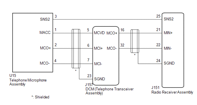 w/o Manual (SOS) Switch
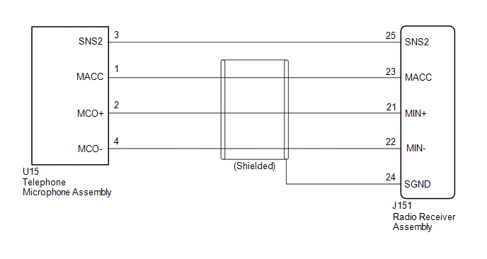
CAUTION / NOTICE / HINT
NOTICE:
-
Depending on the parts that are replaced during vehicle inspection or maintenance, performing initialization, registration or calibration may be needed. Refer to Precaution for Audio and Visual System.
Click here
.gif)
-
Before replacing the DCM (telematics transceiver), refer to Registration.
Click here
PROCEDURE
| 1. | CHECK MICROPHONE (OPERATION CHECK) |
| (a) Enter the "Microphone Check" screen. Refer to Check Microphone (Input to radio receiver assembly) in Operation Check. Click here |
|
.png)
(b) When voice is input into the microphone, check that the microphone input level meter changes according to the input voice.
OK:
Check result is normal.
| OK | .gif) | PROCEED TO NEXT SUSPECTED AREA SHOWN IN PROBLEM SYMPTOMS TABLE |
|
.gif)
| 2. | CHECK MODEL |
(a) Choose the model to be inspected.
| Result | Proceed to |
|---|---|
| w/ Manual (SOS) Switch | A |
| w/o Manual (SOS) Switch | B |
| B | | GO TO STEP 9 |
|
| 3. | CHECK HARNESS AND CONNECTOR (RADIO RECEIVER ASSEMBLY - TELEPHONE MICROPHONE ASSEMBLY) |
(a) Disconnect the J151 radio receiver assembly connector.
(b) Disconnect the U15 telephone microphone assembly connector.
(c) Measure the resistance according to the value(s) in the table below.
Standard Resistance:
| Tester Connection | Condition | Specified Condition |
|---|---|---|
| J151-25 (SNS2) - U15-3 (SNS2) | Always | Below 1 Ω |
| J151-25 (SNS2) or U15-3 (SNS2) - Body ground | Always | 10 kΩ or higher |
| NG | | REPAIR OR REPLACE HARNESS OR CONNECTOR |
|
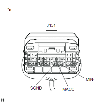
| 4. | CHECK HARNESS AND CONNECTOR (RADIO RECEIVER ASSEMBLY - DCM (TELEMATICS TRANSCEIVER)) |
(a) Disconnect the J151 radio receiver assembly connector.
(b) Disconnect the J157 DCM (telematics transceiver) connector.
(c) Measure the resistance according to the value(s) in the table below.
Standard Resistance:
| Tester Connection | Condition | Specified Condition |
|---|---|---|
| J151-21 (MIN+) - J157-16 (MCO+) | Always | Below 1 Ω |
| J151-22 (MIN-) - J157-32 (MCO-) | Always | Below 1 Ω |
| J151-21 (MIN+) or J157-16 (MCO+) - Body ground | Always | 10 kΩ or higher |
| J151-22 (MIN-) or J157-32 (MCO-) - Body ground | Always | 10 kΩ or higher |
| J151-24 (SGND) - Body ground | Always | 10 kΩ or higher |
| NG | | REPAIR OR REPLACE HARNESS OR CONNECTOR |
|
| 5. | CHECK HARNESS AND CONNECTOR (DCM (TELEMATICS TRANSCEIVER) - TELEPHONE MICROPHONE ASSEMBLY) |
(a) Disconnect the J157 DCM (telematics transceiver) connector.
(b) Disconnect the U15 telephone microphone assembly connector.
(c) Measure the resistance according to the value(s) in the table below.
Standard Resistance:
| Tester Connection | Condition | Specified Condition |
|---|---|---|
| J157-5 (MCVD) - U15-1 (MACC) | Always | Below 1 Ω |
| J157-6 (MCI+) - U15-2 (MCO+) | Always | Below 1 Ω |
| J157-7 (MCI-) - U15-4 (MCO-) | Always | Below 1 Ω |
| J157-5 (MCVD) or U15-1 (MACC) - Body ground | Always | 10 kΩ or higher |
| J157-6 (MCI+) or U15-2 (MCO+) - Body ground | Always | 10 kΩ or higher |
| J157-7 (MCI-) or U15-4 (MCO-) - Body ground | Always | 10 kΩ or higher |
| J157-23 (SGND) - Body ground | Always | 10 kΩ or higher |
| NG | | REPAIR OR REPLACE HARNESS OR CONNECTOR |
|
| 6. | CHECK DCM (TELEMATICS TRANSCEIVER) |
| (a) Remove the DCM (telematics transceiver) with the connector(s) still connected. |
|
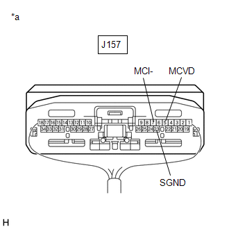
(b) Measure the voltage according to the value(s) in the table below.
Standard Voltage:
| Tester Connection | Condition | Specified Condition |
|---|---|---|
| J157-5 (MCVD) - Body ground | Engine switch on (ACC) | 4 to 6 V |
(c) Measure the resistance according to the value(s) in the table below.
Standard Resistance:
| Tester Connection | Condition | Specified Condition |
|---|---|---|
| J157-23 (SGND) - Body ground | Always | Below 1 Ω |
| J157-7 (MCI-) - Body ground | Always | Below 1 Ω |
| NG | | REPLACE DCM (TELEMATICS TRANSCEIVER) |
|
| 7. | CHECK TELEPHONE MICROPHONE ASSEMBLY (OUTPUT TO DCM (TELEMATICS TRANSCEIVER)) |
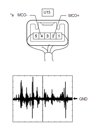
| *a | Component with harness connected (Telephone Microphone Assembly) |
(a) Check the output waveform.
(1) Remove the telephone microphone assembly with the connector(s) still connected.
Click here
(2) Connect an oscilloscope to terminal U15-2 (MCO+) and U15-4 (MCO-).
(3) Turn the engine switch on (ACC).
(4) Sound is input to the telephone microphone assembly when the user is closer than 125 mm from the telephone microphone assembly sound holes in the roof headlining holder cover.
(5) Check the signal waveform according to the condition(s) in the table below.
| Item | Condition |
|---|---|
| Measurement terminal | U15-2 (MCO+) - U15-4 (MCO-) |
| Tool setting | 50 mV/DIV., 500 ms/DIV. |
| Vehicle condition |
|
OK:
The waveform is similar to that shown in the illustration.
HINT:
The oscilloscope waveform shown in the illustration is an example for reference only.
| NG | | REPLACE TELEPHONE MICROPHONE ASSEMBLY |
|
| 8. | CHECK DCM (TELEMATICS TRANSCEIVER) (OUTPUT TO RADIO RECEIVER ASSEMBLY) |
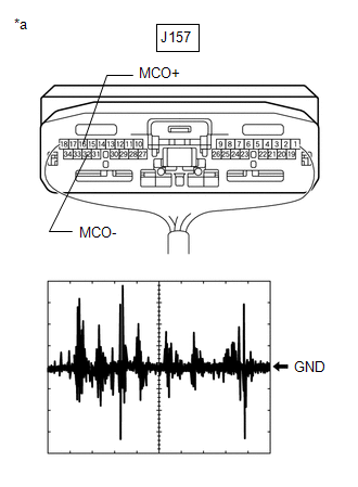
| *a | Component with harness connected (DCM (Telematics Transceiver)) |
(a) Check the output waveform.
(1) Remove the DCM (telematics transceiver) with the connector(s) still connected.
Click here
(2) Connect an oscilloscope to terminal J157-16 (MCO+) and J157-32 (MCO-).
(3) Turn the engine switch on (ACC).
(4) Sound is input to the telephone microphone assembly when the user is closer than 125 mm from the telephone microphone assembly sound holes in the roof headlining holder cover.
(5) Check the signal waveform according to the condition(s) in the table below.
| Item | Condition |
|---|---|
| Measurement terminal | J157-16 (MCO+) - J157-32 (MCO-) |
| Tool setting | 50 mV/DIV., 500 ms/DIV. |
| Vehicle condition |
|
OK:
The waveform is similar to that shown in the illustration.
HINT:
The oscilloscope waveform shown in the illustration is an example for reference only.
| OK | | REPLACE RADIO RECEIVER ASSEMBLY |
| NG | | REPLACE DCM (TELEMATICS TRANSCEIVER) |
| 9. | CHECK HARNESS AND CONNECTOR (RADIO RECEIVER ASSEMBLY - TELEPHONE MICROPHONE ASSEMBLY) |
(a) Disconnect the J151 radio receiver assembly connector.
(b) Disconnect the U15 telephone microphone assembly connector.
(c) Measure the resistance according to the value(s) in the table below.
Standard Resistance:
| Tester Connection | Condition | Specified Condition |
|---|---|---|
| J151-25 (SNS2) - U15-3 (SNS2) | Always | Below 1 Ω |
| J151-23 (MACC) - U15-1 (MACC) | Always | Below 1 Ω |
| J151-21 (MIN+) - U15-2 (MCO+) | Always | Below 1 Ω |
| J151-22 (MIN-) - U15-4 (MCO-) | Always | Below 1 Ω |
| J151-25 (SNS2) or U15-3 (SNS2) - Body ground | Always | 10 kΩ or higher |
| J151-23 (MACC) or U15-1 (MACC) - Body ground | Always | 10 kΩ or higher |
| J151-21 (MIN+) or U15-2 (MCO+) - Body ground | Always | 10 kΩ or higher |
| J151-22 (MIN-) or U15-4 (MCO-) - Body ground | Always | 10 kΩ or higher |
| J151-24 (SGND) - Body ground | Always | 10 kΩ or higher |
| NG | | REPAIR OR REPLACE HARNESS OR CONNECTOR |
|
| 10. | CHECK RADIO RECEIVER ASSEMBLY |
| (a) Remove the radio receiver assembly with the connector(s) still connected. |
|
(b) Measure the voltage according to the value(s) in the table below.
Standard Voltage:
| Tester Connection | Condition | Specified Condition |
|---|---|---|
| J151-23 (MACC) - Body ground | Engine switch on (ACC) | 4 to 6 V |
(c) Measure the resistance according to the value(s) in the table below.
Standard Resistance:
| Tester Connection | Condition | Specified Condition |
|---|---|---|
| J151-22 (MIN-) - Body ground | Always | Below 1 Ω |
| J151-24 (SGND) - Body ground | Always | Below 1 Ω |
| NG | | REPLACE RADIO RECEIVER ASSEMBLY |
|
| 11. | CHECK TELEPHONE MICROPHONE ASSEMBLY (OUTPUT TO RADIO RECEIVER ASSEMBLY) |

| *a | Component with harness connected (Telephone Microphone Assembly) |
(a) Check the output waveform.
(1) Remove the telephone microphone assembly with the connector(s) still connected.
Click here
(2) Connect an oscilloscope to terminal U15-2 (MCO+) and U15-4 (MCO-).
(3) Turn the engine switch on (ACC).
(4) Sound is input to the telephone microphone assembly when the user is closer than 125 mm from the telephone microphone assembly sound holes in the roof headlining holder cover.
(5) Check the signal waveform according to the condition(s) in the table below.
| Item | Condition |
|---|---|
| Measurement terminal | U15-2 (MCO+) - U15-4 (MCO-) |
| Tool setting | 50 mV/DIV., 500 ms/DIV. |
| Vehicle condition |
|
OK:
The waveform is similar to that shown in the illustration.
HINT:
The oscilloscope waveform shown in the illustration is an example for reference only.
| OK | | REPLACE RADIO RECEIVER ASSEMBLY |
| NG | | REPLACE TELEPHONE MICROPHONE ASSEMBLY |
 Voice Guidance Circuit between Radio Receiver and Stereo Component Amplifier
DESCRIPTION Using this circuit, the radio receiver assembly sends signals to the stereo component amplifier assembly. WIRING DIAGRAM PROCEDURE 1. CHECK HARNESS AND CONNECTOR (RADIO RECEIVER ASS ...
 Visual Mute Signal Circuit between Radio Receiver and Multi-display
DESCRIPTION The radio receiver assembly sends a visual mute signal to the multi-display assembly. As a result, a black screen is displayed when the screen changes so that noise and distorted images ar ...
Other materials:
Lexus RX (RX 350L, RX450h) 2016-2026 Repair Manual > Dynamic Torque Control Awd System: Parts Location
PARTS LOCATION ILLUSTRATION *1 ECM *2 SKID CONTROL ECU (BRAKE ACTUATOR ASSEMBLY) *3 ELECTRO MAGNETIC CONTROL COUPLING SUB-ASSEMBLY - 4WD LINEAR SOLENOID *4 ENGINE ROOM RELAY BLOCK AND JUNCTION BLOCK ASSEMBLY - ECU-IG1 NO. 5 FUSE ILLUSTRATION *A w/o AVS *B w/ AVS ...
Lexus RX (RX 350L, RX450h) 2016-2026 Repair Manual > Automatic Transaxle System: Precaution
PRECAUTION PRECAUTION FOR DISCONNECTING CABLE FROM NEGATIVE BATTERY TERMINAL NOTICE: When disconnecting the cable from the negative (-) battery terminal, initialize the following system(s) after the cable is reconnected: System See Procedure Lane Control System Pre-collision System ...
Lexus RX (RX 350L, RX450h) 2016-{YEAR} Owners Manual
- For your information
- Pictorial index
- For safety and security
- Instrument cluster
- Operation of each component
- Driving
- Lexus Display Audio system
- Interior features
- Maintenance and care
- When trouble arises
- Vehicle specifications
- For owners
Lexus RX (RX 350L, RX450h) 2016-{YEAR} Repair Manual

0.0105