Lexus RX (RX 350L, RX450h) 2016-2026 Repair Manual: Visual Mute Signal Circuit between Radio Receiver and Multi-display
DESCRIPTION
The radio receiver assembly sends a visual mute signal to the multi-display assembly. As a result, a black screen is displayed when the screen changes so that noise and distorted images are not displayed.
When an open exists in the circuit, noise and distorted images will be displayed instead of a black screen.
When a short exists in the circuit, even though the multi-display assembly is operating normally, noise and distorted images will be displayed (black screen will not be displayed) during screen changes or the black screen will always be displayed.
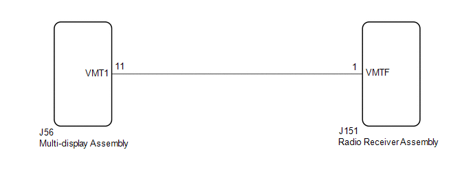
WIRING DIAGRAM
CAUTION / NOTICE / HINT
NOTICE:
Depending on the parts that are replaced during vehicle inspection or maintenance, performing initialization, registration or calibration may be needed. Refer to Precaution for Audio and Visual System.
Click here .gif)
PROCEDURE
| 1. | INSPECT MULTI-DISPLAY ASSEMBLY |
| (a) Measure the voltage according to the value(s) in the table below. Standard Voltage:
|
|
| OK |  | PROCEED TO NEXT SUSPECTED AREA SHOWN IN PROBLEM SYMPTOMS TABLE |
|

| 2. | CHECK HARNESS AND CONNECTOR (RADIO RECEIVER ASSEMBLY - MULTI-DISPLAY ASSEMBLY) |
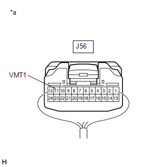
(a) Disconnect the J56 multi-display assembly connector.
(b) Disconnect the J151 radio receiver assembly connector.
(c) Measure the resistance according to the value(s) in the table below.
Standard Resistance:
| Tester Connection | Condition | Specified Condition |
|---|---|---|
| J151-1 (VMTF) - J56-11 (VMT1) | Always | Below 1 Ω |
| J151-1 (VMTF) or J56-11 (VMT1) - Body ground | Always | 10 kΩ or higher |
| NG | | REPAIR OR REPLACE HARNESS OR CONNECTOR |
|
| 3. | REPLACE MULTI-DISPLAY ASSEMBLY |
(a) Replace the multi-display assembly with a new or known good one.
Click here
(b) Check that the screen display is normal.
OK:
Screen display is normal.
| OK | | END |
| NG | | REPLACE RADIO RECEIVER ASSEMBLY |
 Microphone Circuit
DESCRIPTION
The radio receiver assembly and telephone microphone assembly are connected to each other using the microphone connection detection signal lines.
Using this circuit, the radio receive ...
 Radio Receiver Power Source Circuit
DESCRIPTION This is the power source circuit to operate the radio receiver assembly. WIRING DIAGRAM CAUTION / NOTICE / HINT NOTICE: Inspect the fuses for circuits related to this system before perfor ...
Other materials:
Lexus RX (RX 350L, RX450h) 2016-2026 Repair Manual > Seat Belt Warning System: Parts Location
PARTS LOCATION ILLUSTRATION *1 AIRBAG SENSOR ASSEMBLY *2 ECM *3 SKID CONTROL ECU (BRAKE ACTUATOR ASSEMBLY) *4 DLC3 *5 MAIN BODY ECU (MULTIPLEX NETWORK BODY ECU) *6 INSTRUMENT PANEL JUNCTION BLOCK ASSEMBLY *7 ENGINE ROOM RELAY BLOCK AND JUNCTION BLOCK ASSEMBLY - EC ...
Lexus RX (RX 350L, RX450h) 2016-2026 Repair Manual > Can Communication System: DCM Communication Stop Mode
DESCRIPTION Detection Item Symptom Trouble Area DCM Communication Stop Mode Either condition is met:
"DCM" is not displayed on the CAN Bus Check screen of the Techstream.
Click here
Communication system DTCs (DTCs that start with U) that correspond to "DCM Communication Stop Mode ...
Lexus RX (RX 350L, RX450h) 2016-{YEAR} Owners Manual
- For your information
- Pictorial index
- For safety and security
- Instrument cluster
- Operation of each component
- Driving
- Lexus Display Audio system
- Interior features
- Maintenance and care
- When trouble arises
- Vehicle specifications
- For owners
Lexus RX (RX 350L, RX450h) 2016-{YEAR} Repair Manual

0.0099