Lexus RX (RX 350L, RX450h) 2016-2026 Repair Manual: Radio Receiver Power Source Circuit
DESCRIPTION
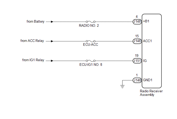
This is the power source circuit to operate the radio receiver assembly.
WIRING DIAGRAM
CAUTION / NOTICE / HINT
NOTICE:
Inspect the fuses for circuits related to this system before performing the following procedure.
PROCEDURE
| 1. | CHECK HARNESS AND CONNECTOR (RADIO RECEIVER ASSEMBLY POWER SOURCE) |
(a) Disconnect the J151 and J148 radio receiver assembly connectors.
(b) Measure the resistance according to the value(s) in the table below.
Standard Resistance:
| Tester Connection | Condition | Specified Condition |
|---|---|---|
| J148-1 (GND1) - Body ground | Always | Below 1 Ω |
(c) Measure the voltage according to the value(s) in the table below.
Standard Voltage:
| Tester Connection | Condition | Specified Condition |
|---|---|---|
| J148-4 (+B1) - J148-1 (GND1) | Always | 11 to 14 V |
| J148-15 (ACC1) - J148-1 (GND1) | Engine switch on (ACC) | 11 to 14 V |
| J151-19 (IG) - J148-1 (GND1) | Engine switch on (IG) | 11 to 14 V |
| OK | .gif) | PROCEED TO NEXT SUSPECTED AREA SHOWN IN PROBLEM SYMPTOMS TABLE |
| NG | | REPAIR OR REPLACE HARNESS OR CONNECTOR |
 Visual Mute Signal Circuit between Radio Receiver and Multi-display
DESCRIPTION The radio receiver assembly sends a visual mute signal to the multi-display assembly. As a result, a black screen is displayed when the screen changes so that noise and distorted images ar ...

Other materials:
Lexus RX (RX 350L, RX450h) 2016-2026 Repair Manual > Lexus Enform System: Operation Check
OPERATION CHECK LEXUS APP SUITE RESET PROCEDURE (a) Duplicate the problem symptom. (b) Check for DTCs and repair the systems for which any DTCs are output. Click here (c) Check cellular phone compatibility. (1) Check if the cellular phone/vehicle is compatible (Refer to http://www.lexus.com/Mobile ...
Lexus RX (RX 350L, RX450h) 2016-2026 Repair Manual > Front Door Lock: Components
COMPONENTS ILLUSTRATION *A for Driver Side *B for Front Passenger Side *1 COURTESY LIGHT ASSEMBLY *2 DOOR ARMREST COVER *3 FRONT DOOR INSIDE HANDLE BEZEL PLUG *4 FRONT DOOR NO. 1 STIFFENER CUSHION *5 FRONT DOOR TRIM BOARD SUB-ASSEMBLY *6 MULTIPLEX NETWORK MAST ...
Lexus RX (RX 350L, RX450h) 2016-{YEAR} Owners Manual
- For your information
- Pictorial index
- For safety and security
- Instrument cluster
- Operation of each component
- Driving
- Lexus Display Audio system
- Interior features
- Maintenance and care
- When trouble arises
- Vehicle specifications
- For owners
Lexus RX (RX 350L, RX450h) 2016-{YEAR} Repair Manual

0.0098