Lexus RX (RX 350L, RX450h) 2016-2026 Repair Manual: Lost Communication with Rear Panel LIN (B14B3)
DESCRIPTION
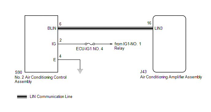
The No. 2 air conditioning control assembly communicates with the air conditioning amplifier assembly via LIN communication.
If the LIN communication system is malfunctioning, the air conditioning amplifier assembly does not operate even if the No. 2 air conditioning control assembly is operated.
| DTC No. | Detection Item | DTC Detection Condition | Trouble Area | Memory |
|---|---|---|---|---|
| B14B3 | Lost Communication with Rear Panel LIN | Lost communication with No. 2 air conditioning control assembly |
| Memorized (10 sec. or more)* |
- *: The air conditioning amplifier assembly stores this DTC if the malfunction has occurred for the period of time indicated in the brackets.
WIRING DIAGRAM
CAUTION / NOTICE / HINT
NOTICE:
Inspect the fuses for circuits related to this system before performing the following procedure.
PROCEDURE
| 1. | CHECK HARNESS AND CONNECTOR (NO. 2 AIR CONDITIONING CONTROL ASSEMBLY - IG POWER SOURCE) |
(a) Disconnect the S90 No. 2 air conditioning control assembly connector.
(b) Measure the voltage according to the value(s) in the table below.
Standard Voltage:
| Tester Connection | Condition | Specified Condition |
|---|---|---|
| S90-2 (IG) - Body ground | Engine switch off | Below 1 V |
| S90-2 (IG) - Body ground | Engine switch on (IG) | 11 to 14 V |
| NG | .gif) | REPAIR OR REPLACE HARNESS OR CONNECTOR |
|
.gif)
| 2. | CHECK HARNESS AND CONNECTOR (NO. 2 AIR CONDITIONING CONTROL ASSEMBLY - BODY GROUND) |
(a) Measure the resistance according to the value(s) in the table below.
Standard Resistance:
| Tester Connection | Condition | Specified Condition |
|---|---|---|
| S90-4 (E) - Body ground | Always | Below 1 Ω |
| NG | | REPAIR OR REPLACE HARNESS OR CONNECTOR |
|
| 3. | CHECK HARNESS AND CONNECTOR (NO. 2 AIR CONDITIONING CONTROL ASSEMBLY - AIR CONDITIONING AMPLIFIER ASSEMBLY) |
(a) Disconnect the J43 air conditioning amplifier assembly connector.
(b) Measure the resistance according to the value(s) in the table below.
Standard Resistance:
| Tester Connection | Condition | Specified Condition |
|---|---|---|
| S90-6 (BLIN) - J43-16 (LIN3) | Always | Below 1 Ω |
| S90-6 (BLIN) or J43-16 (LIN3) - Other terminals and body ground | Always | 10 kΩ or higher |
| NG | | REPAIR OR REPLACE HARNESS OR CONNECTOR |
|
| 4. | REPLACE NO. 2 AIR CONDITIONING HARNESS ASSEMBLY |
(a) Replace the No. 2 air conditioning control assembly.
Click here .gif)
HINT:
Since the No. 2 air conditioning control assembly cannot be inspected while it is removed from the vehicle, replace the No. 2 air conditioning control assembly with a new or known good one and check that the condition returns to normal.
OK:
No. 2 air conditioning control assembly operation returns to normal.
| Result | Proceed to |
|---|---|
| OK | A |
| NG (When troubleshooting according to Problem Symptoms Table) | B |
| NG (When troubleshooting according to the DTC) | C |
| A | | END (NO. 2 AIR CONDITIONING CONTROL ASSEMBLY WAS DEFECTIVE) |
| B | | PROCEED TO NEXT SUSPECTED AREA SHOWN IN PROBLEM SYMPTOMS TABLE |
| C | | REPLACE AIR CONDITIONING AMPLIFIER ASSEMBLY |
 BUS IC Communication Malfunction (B1497/97)
DESCRIPTION Front Air Conditioning System The air conditioning harness assembly connects the air conditioning amplifier assembly and the servo motors. The air conditioning amplifier assembly supplies ...
 Refrigerant Shortage (B14B8)
DESCRIPTION This DTC is stored if the amount of refrigerant in the air conditioning system is insufficient. The air conditioning amplifier assembly receives the ambient temperature signal, refrigerant ...
Other materials:
Lexus RX (RX 350L, RX450h) 2016-2026 Repair Manual > Sliding Roof System: Initialization
INITIALIZATION INITIALIZE SLIDING ROOF SYSTEM NOTICE:
When the sliding roof glass sub-assembly or sliding roof drive cable sub-assembly is adjusted or removed/installed, or the sliding roof drive gear sub-assembly is replaced, the sliding roof ECU (sliding roof drive gear sub-assembly) must be in ...
Lexus RX (RX 350L, RX450h) 2016-2026 Repair Manual > Pre-collision System: Parts Location
PARTS LOCATION ILLUSTRATION *1 FORWARD RECOGNITION CAMERA *2 MILLIMETER WAVE RADAR SENSOR ASSEMBLY *3 BRAKE ACTUATOR ASSEMBLY - SKID CONTROL ECU *4 ECM ILLUSTRATION *A w/o VDIM *B w/ VDIM *1 AIRBAG SENSOR ASSEMBLY - YAW RATE SENSOR *2 YAW RATE SENSOR ASSEMB ...
Lexus RX (RX 350L, RX450h) 2016-{YEAR} Owners Manual
- For your information
- Pictorial index
- For safety and security
- Instrument cluster
- Operation of each component
- Driving
- Lexus Display Audio system
- Interior features
- Maintenance and care
- When trouble arises
- Vehicle specifications
- For owners
Lexus RX (RX 350L, RX450h) 2016-{YEAR} Repair Manual

0.0144