Lexus RX (RX 350L, RX450h) 2016-2026 Repair Manual: BUS IC Communication Malfunction (B1497/97)
DESCRIPTION
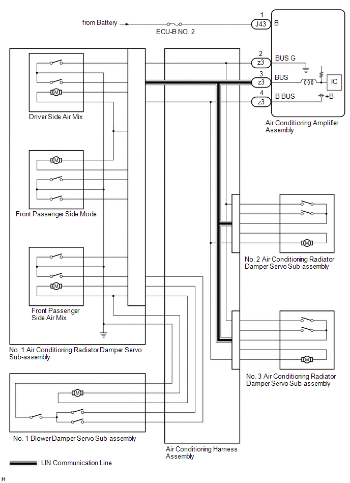
Front Air Conditioning SystemThe air conditioning harness assembly connects the air conditioning amplifier assembly and the servo motors. The air conditioning amplifier assembly supplies power and sends operation instructions to each servo motor through the air conditioning harness assembly. Each servo motor sends damper position information to the air conditioning amplifier assembly.
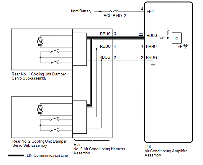
Rear Air Conditioning System (w/ Rear Air Conditioning System)The No. 2 air conditioning harness assembly connects the air conditioning amplifier assembly and the servo motors. The air conditioning amplifier assembly supplies power and sends operation instructions to each servo motor through the No. 2 air conditioning harness assembly. Each servo motor sends damper position information to the air conditioning amplifier assembly.
| DTC No. | Detection Item | DTC Detection Condition | Trouble Area | Memory |
|---|---|---|---|---|
| B1497/97 | BUS IC Communication Malfunction | Error or open in communication line |
| Memorized (10 sec. or more)*1 |
- *1: The air conditioning amplifier assembly stores this DTC if the malfunction has occurred for the period of time indicated in the brackets.
- *2: w/ Rear Air Conditioning System
WIRING DIAGRAM
FRONT AIR CONDITIONING SYSTEM
REAR AIR CONDITIONING SYSTEM (w/ Rear Air Conditioning System)
CAUTION / NOTICE / HINT
NOTICE:
Inspect the fuses for circuits related to this system before performing the following procedure.
PROCEDURE
| 1. | CHECK HARNESS AND CONNECTOR (POWER SOURCE CIRCUIT) |
(a) Disconnect the J43 and J48* air conditioning amplifier assembly connector.
(b) Measure the voltage according to the value(s) in the table below.
Standard Voltage:
| Tester Connection | Condition | Specified Condition |
|---|---|---|
| J43-1 (B) - Body ground | Engine switch off | 11 to 14 V |
| J48-4 (+B2) - Body ground* | Engine switch off | 11 to 14 V |
- *: w/ Rear Air Conditioning System
| NG | .gif) | REPAIR OR REPLACE HARNESS OR CONNECTOR |
|
.gif)
| 2. | PERFORM ACTIVE TEST USING TECHSTREAM |
(a) Connect the J43 and J48* air conditioning amplifier assembly connector.
(b) Connect the Techstream to the DLC3.
(c) Turn the engine switch on (IG).
(d) Turn the Techstream on.
(e) Enter the following menus: Body Electrical / Air Conditioner / Active test.
(f) Perform the Active Test according to the display on the Techstream.
Body Electrical > Air Conditioner > Active Test| Tester Display | Measurement Item | Control Range | Diagnostic Note |
|---|---|---|---|
| Air Mix Servo Targ Pulse(D) | No. 1 air conditioning radiator damper servo sub-assembly (driver side air mix) pulse | Min.: 128 Max.: 383 | Operates between 165 to 257 pulses |
| Air Mix Servo Targ Pulse(P) | No. 1 air conditioning radiator damper servo sub-assembly (front passenger side air mix) pulse | Min.: 128 Max.: 383 | Operates between 255 to 347 pulses |
| Air Outlet Servo Pulse (D) | No. 3 air conditioning radiator damper servo sub-assembly pulse | Min.: 128 Max.: 383 | Operates between 164 to 256 pulses |
| Air Inlet Damper Targ Pulse | No. 1 blower damper servo sub-assembly pulse | Min.: 128 Max.: 383 | Operates between 220 to 256 pulses |
| Rear Air Mix Servo Targ Pulse | Rear No. 2 cooling unit damper servo sub-assembly pulse* | Min.: 128 Max.: 383 | Operates between 254 to 299 pulses |
| Air Outlet Servo Pulse (P) | No. 1 air conditioning radiator damper servo sub-assembly (front passenger side mode) pulse | Min.: 128 Max.: 383 | Operates between 256 to 348 pulses |
| A/O Servo Pulse(F&R D) | Rear No. 1 cooling unit damper servo sub-assembly pulse* | Min.: 128 Max.: 383 | Operates between 200 to 276 pulses |
| A/O Servo Pulse(Rr D) | No. 2 air conditioning radiator damper servo sub-assembly pulse | Min.: 128 Max.: 383 | Operates between 158 to 260 pulses |
| Tester Display |
|---|
| Air Mix Servo Targ Pulse(D) |
| Tester Display |
|---|
| Air Mix Servo Targ Pulse(P) |
| Tester Display |
|---|
| Air Outlet Servo Pulse (D) |
| Tester Display |
|---|
| Air Inlet Damper Targ Pulse |
| Tester Display |
|---|
| Rear Air Mix Servo Targ Pulse |
| Tester Display |
|---|
| Air Outlet Servo Pulse (P) |
| Tester Display |
|---|
| A/O Servo Pulse(F&R D) |
| Tester Display |
|---|
| A/O Servo Pulse(Rr D) |
- *: w/ Rear Air Conditioning System
OK:
Arm of the damper servo motor selected in the Active Test operates smoothly.
(g) According to the test result, proceed to the next step.
| Result | Proceed to |
|---|---|
| All of the damper servo motors are normal | A |
| One of the damper servo motors is malfunctioning | B |
| All of the front damper servo motors are malfunctioning | C |
| All of the rear damper servo motors are malfunctioning | D |
| A | | REPLACE AIR CONDITIONING AMPLIFIER ASSEMBLY |
| C | | GO TO STEP 10 |
| D | | GO TO STEP 11 |
|
| 3. | SYSTEM CHECK |
(a) According to the test result, proceed to the next step.
| Result | Proceed to |
|---|---|
| Only the No. 1 blower damper servo sub-assembly is malfunctioning | A |
| Only the No. 1 air conditioning radiator damper servo sub-assembly (driver side air mix) is malfunctioning | B |
| Only the No. 1 air conditioning radiator damper servo sub-assembly (front passenger side air mix) is malfunctioning | |
| Only the No. 1 air conditioning radiator damper servo sub-assembly (front passenger side mode) is malfunctioning | |
| Only the No. 2 air conditioning radiator damper servo sub-assembly is malfunctioning | C |
| Only the No. 3 air conditioning radiator damper servo sub-assembly is malfunctioning | D |
| Only the rear No. 1 cooling unit damper servo sub-assembly is malfunctioning | E |
| Only the rear No. 2 cooling unit damper servo sub-assembly is malfunctioning | F |
| B | | GO TO STEP 5 |
| C | | GO TO STEP 6 |
| D | | GO TO STEP 7 |
| E | | GO TO STEP 8 |
| F | | GO TO STEP 9 |
|
| 4. | REPLACE NO. 1 BLOWER DAMPER SERVO SUB-ASSEMBLY |
(a) Replace the No. 1 blower damper servo sub-assembly.
Click here .gif)
HINT:
Since the servo motor cannot be inspected while it is removed from the vehicle, replace the servo motor with a new or known good one and check that the condition returns to normal.
(b) Connect the Techstream to the DLC3.
(c) Turn the engine switch on (IG).
(d) Turn the Techstream on.
(e) Enter the following menus: Body Electrical / Air Conditioner / Trouble Codes.
(f) Check for DTCs.
Body Electrical > Air Conditioner > Trouble Codes| Result | Proceed to |
|---|---|
| DTC B1497/97 is not output | A |
| DTC B1497/97 is output | B |
| A | | END (NO. 1 BLOWER DAMPER SERVO SUB-ASSEMBLY WAS DEFECTIVE) |
| B | | GO TO STEP 5 |
| 5. | REPLACE NO. 1 AIR CONDITIONING RADIATOR DAMPER SERVO SUB-ASSEMBLY |
(a) Replace the No. 1 air conditioning radiator damper servo sub-assembly.
Click here
HINT:
Since the servo motor cannot be inspected while it is removed from the vehicle, replace the servo motor with a new or known good one and check that the condition returns to normal.
(b) Connect the Techstream to the DLC3.
(c) Turn the engine switch on (IG).
(d) Turn the Techstream on.
(e) Enter the following menus: Body Electrical / Air Conditioner / Trouble Codes.
(f) Check for DTCs.
Body Electrical > Air Conditioner > Trouble Codes| Result | Proceed to |
|---|---|
| DTC B1497/97 is not output | A |
| DTC B1497/97 is output | B |
| A | | END (NO. 1 AIR CONDITIONING RADIATOR DAMPER SERVO SUB-ASSEMBLY WAS DEFECTIVE) |
| B | | GO TO STEP 10 |
| 6. | REPLACE NO. 2 AIR CONDITIONING RADIATOR DAMPER SERVO SUB-ASSEMBLY |
(a) Replace the No. 2 air conditioning radiator damper servo sub-assembly.
Click here
HINT:
Since the servo motor cannot be inspected while it is removed from the vehicle, replace the servo motor with a new or known good one and check that the condition returns to normal.
(b) Connect the Techstream to the DLC3.
(c) Turn the engine switch on (IG).
(d) Turn the Techstream on.
(e) Enter the following menus: Body Electrical / Air Conditioner / Trouble Codes.
(f) Check for DTCs.
Body Electrical > Air Conditioner > Trouble Codes| Result | Proceed to |
|---|---|
| DTC B1497/97 is not output | A |
| DTC B1497/97 is output | B |
| A | | END (NO. 2 AIR CONDITIONING RADIATOR DAMPER SERVO SUB-ASSEMBLY WAS DEFECTIVE) |
| B | | GO TO STEP 10 |
| 7. | REPLACE NO. 3 AIR CONDITIONING RADIATOR DAMPER SERVO SUB-ASSEMBLY |
(a) Replace the No. 3 air conditioning radiator damper servo sub-assembly.
Click here
HINT:
Since the servo motor cannot be inspected while it is removed from the vehicle, replace the servo motor with a new or known good one and check that the condition returns to normal.
(b) Connect the Techstream to the DLC3.
(c) Turn the engine switch on (IG).
(d) Turn the Techstream on.
(e) Enter the following menus: Body Electrical / Air Conditioner / Trouble Codes.
(f) Check for DTCs.
Body Electrical > Air Conditioner > Trouble Codes| Result | Proceed to |
|---|---|
| DTC B1497/97 is not output | A |
| DTC B1497/97 is output | B |
| A | | END (NO. 3 AIR CONDITIONING RADIATOR DAMPER SERVO SUB-ASSEMBLY WAS DEFECTIVE) |
| B | | GO TO STEP 10 |
| 8. | REPLACE REAR NO. 1 COOLING UNIT DAMPER SERVO SUB-ASSEMBLY |
(a) Replace the rear No. 1 cooling unit damper servo sub-assembly.
Click here
HINT:
Since the servo motor cannot be inspected while it is removed from the vehicle, replace the servo motor with a new or known good one and check that the condition returns to normal.
(b) Connect the Techstream to the DLC3.
(c) Turn the engine switch on (IG).
(d) Turn the Techstream on.
(e) Enter the following menus: Body Electrical / Air Conditioner / Trouble Codes.
(f) Check for DTCs.
Body Electrical > Air Conditioner > Trouble Codes| Result | Proceed to |
|---|---|
| DTC B1497/97 is not output | A |
| DTC B1497/97 is output | B |
| A | | END (REAR NO. 1 COOLING UNIT DAMPER SERVO SUB-ASSEMBLY WAS DEFECTIVE) |
| B | | GO TO STEP 11 |
| 9. | REPLACE REAR NO. 2 COOLING UNIT DAMPER SERVO SUB-ASSEMBLY |
(a) Replace the rear No. 2 cooling unit damper servo sub-assembly.
Click here
HINT:
Since the servo motor cannot be inspected while it is removed from the vehicle, replace the servo motor with a new or known good one and check that the condition returns to normal.
(b) Connect the Techstream to the DLC3.
(c) Turn the engine switch on (IG).
(d) Turn the Techstream on.
(e) Enter the following menus: Body Electrical / Air Conditioner / Trouble Codes.
(f) Check for DTCs.
Body Electrical > Air Conditioner > Trouble Codes| Result | Proceed to |
|---|---|
| DTC B1497/97 is not output | A |
| DTC B1497/97 is output | B |
| A | | END (REAR NO. 2 COOLING UNIT DAMPER SERVO SUB-ASSEMBLY WAS DEFECTIVE) |
| B | | GO TO STEP 11 |
| 10. | REPLACE AIR CONDITIONING HARNESS ASSEMBLY |
(a) Replace the air conditioning harness assembly.
Click here
HINT:
Since the air conditioning harness assembly cannot be inspected while it is removed from the vehicle, replace the air conditioning harness assembly with a new or known good one and check that the condition returns to normal.
(b) Connect the Techstream to the DLC3.
(c) Turn the engine switch on (IG).
(d) Turn the Techstream on.
(e) Enter the following menus: Body Electrical / Air Conditioner / Trouble Codes.
(f) Check for DTCs.
Body Electrical > Air Conditioner > Trouble Codes| Result | Proceed to |
|---|---|
| DTC B1497/97 is not output | A |
| DTC B1497/97 is output | B |
| A | | END (AIR CONDITIONING HARNESS ASSEMBLY WAS DEFECTIVE) |
| B | | REPLACE AIR CONDITIONING AMPLIFIER ASSEMBLY |
| 11. | REPLACE NO. 2 AIR CONDITIONING HARNESS ASSEMBLY |
(a) Replace the No. 2 air conditioning harness assembly.
Click here
HINT:
Since the air conditioning harness assembly cannot be inspected while it is removed from the vehicle, replace the air conditioning harness assembly with a new or known good one and check that the condition returns to normal.
(b) Connect the Techstream to the DLC3.
(c) Turn the engine switch on (IG).
(d) Turn the Techstream on.
(e) Enter the following menus: Body Electrical / Air Conditioner / Trouble Codes.
(f) Check for DTCs.
Body Electrical > Air Conditioner > Trouble Codes| Result | Proceed to |
|---|---|
| DTC B1497/97 is not output | A |
| DTC B1497/97 is output | B |
| A | | END (NO. 2 AIR CONDITIONING HARNESS ASSEMBLY WAS DEFECTIVE) |
| B | | REPLACE NO. 2 AIR CONDITIONING HARNESS ASSEMBLY |
 Air Outlet Damper Control Servo Motor Circuit(Driver Side Front A/C Rear Air Flow) (B1486/86)
DESCRIPTION The Rear No. 1 cooling unit damper servo sub-assembly sends pulse signals to inform the air conditioning amplifier assembly of the damper position. The air conditioning amplifier assembly ...
 Lost Communication with Rear Panel LIN (B14B3)
DESCRIPTION The No. 2 air conditioning control assembly communicates with the air conditioning amplifier assembly via LIN communication. If the LIN communication system is malfunctioning, the air cond ...
Other materials:
Lexus RX (RX 350L, RX450h) 2016-2026 Repair Manual > Rear Power Outlet Socket (w/o Rear No. 2 Seat): Installation
INSTALLATION PROCEDURE 1. INSTALL REAR POWER OUTLET SOCKET COVER (a) Engage the 2 claws to install the rear power outlet socket cover as shown in the illustration. Install in this Direction 2. INSTALL REAR NO. 1 POWER OUTLET SOCKET ASSEMBLY (a) Engage the claw to install the clamp to the N ...
Lexus RX (RX 350L, RX450h) 2016-2026 Repair Manual > Road Sign Assist System: Diagnosis System
DIAGNOSIS SYSTEM DIAGNOSIS FUNCTION (a) The road sign assist system displays a warning message on the multi-information display to inform the driver that the system is unavailable when it is malfunctioning. Warning Message Details DTC/RoB RSA Malfunction Visit Your Dealer Road sign assi ...
Lexus RX (RX 350L, RX450h) 2016-{YEAR} Owners Manual
- For your information
- Pictorial index
- For safety and security
- Instrument cluster
- Operation of each component
- Driving
- Lexus Display Audio system
- Interior features
- Maintenance and care
- When trouble arises
- Vehicle specifications
- For owners
Lexus RX (RX 350L, RX450h) 2016-{YEAR} Repair Manual

0.0133