Lexus RX (RX 350L, RX450h) 2016-2026 Repair Manual: Installation
INSTALLATION
PROCEDURE
1. INSTALL REAR POWER OUTLET SOCKET COVER
(a) Engage the 2 claws to install the rear power outlet socket cover as shown in the illustration.
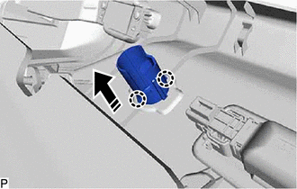
.png) | Install in this Direction |
2. INSTALL REAR NO. 1 POWER OUTLET SOCKET ASSEMBLY
(a) Engage the claw to install the clamp to the No. 1 power outlet socket assembly as shown in the illustration.
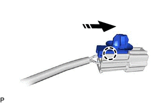
| | Install in this Direction |
(b) Engage the claw to install the rear No. 1 power outlet socket assembly as shown in the illustration.
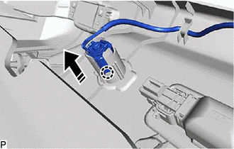
| | Install in this Direction |
3. INSTALL DECK TRIM SIDE PANEL ASSEMBLY LH
Click here .gif)
4. INSTALL NO. 1 LUGGAGE COMPARTMENT LIGHT ASSEMBLY
Click here
5. INSTALL ROPE HOOK ASSEMBLY
Click here
6. INSTALL NO. 1 LUGGAGE COMPARTMENT TRIM HOOK
Click here
7. INSTALL REAR FLOOR FINISH SIDE PLATE LH
Click here
8. INSTALL REAR SEAT SIDE GARNISH LH
Click here
9. INSTALL UPPER QUARTER TRIM PAD LH
Click here
10. INSTALL REAR SEAT ASSEMBLY LH
Click here
11. INSTALL REAR DOOR SCUFF PLATE LH
Click here
12. INSTALL REAR FLOOR FINISH PLATE
Click here
13. INSTALL DECK SIDE TRIM BOX RH
Click here
14. INSTALL FRONT DECK FLOOR BOX
Click here
15. INSTALL REAR NO. 4 FLOOR BOARD
Click here
16. INSTALL REAR DECK FLOOR BOX
Click here
17. INSTALL REAR NO. 3 FLOOR BOARD
Click here
18. INSTALL DECK BOARD ASSEMBLY
Click here
19. INSTALL TONNEAU COVER ASSEMBLY
Click here
 Removal
REMOVAL CAUTION / NOTICE / HINT The necessary procedures (adjustment, calibration, initialization or registration) that must be performed after parts are removed and installed, or replaced during rear ...

Other materials:
Lexus RX (RX 350L, RX450h) 2016-2026 Repair Manual > Front Door Speaker: Inspection
INSPECTION PROCEDURE 1. INSPECT FRONT NO. 1 SPEAKER ASSEMBLY (a) With the speaker installed, check that there is no looseness or other abnormalities. (b) Check that there is no foreign matter in the speaker, no tears on the speaker cone or other abnormalities. (c) Measure the resistance of the sp ...
Lexus RX (RX 350L, RX450h) 2016-2026 Repair Manual > Dynamic Radar Cruise Control System: Lost Communication with ECM/PCM "A" Missing Message (U010087,U010487,U012287)
DESCRIPTION The ECM communicates with each sensor and ECU via CAN communication. If any malfunction is detected in a CAN communication circuit, one or more CAN communication system DTCs are stored. DTC No. Detection Item DTC Detection Condition Trouble Area MIL DTC Output from U0100 ...
Lexus RX (RX 350L, RX450h) 2016-{YEAR} Owners Manual
- For your information
- Pictorial index
- For safety and security
- Instrument cluster
- Operation of each component
- Driving
- Lexus Display Audio system
- Interior features
- Maintenance and care
- When trouble arises
- Vehicle specifications
- For owners
Lexus RX (RX 350L, RX450h) 2016-{YEAR} Repair Manual

0.0131