Lexus RX (RX 350L, RX450h) 2016-2026 Repair Manual: Removal
REMOVAL
CAUTION / NOTICE / HINT
The necessary procedures (adjustment, calibration, initialization or registration) that must be performed after parts are removed and installed, or replaced during rear No. 1 power outlet socket removal/installation are shown below.
Necessary Procedures After Parts Removed/Installed/Replaced| Replaced Part or Performed Procedure | Necessary Procedure | Effect/Inoperative Function when Necessary Procedure not Performed | Link |
|---|---|---|---|
|
*1: When performing learning using the Techstream.
Click here | |||
| Disconnect cable from negative battery terminal | Memorize steering angle neutral point | Lane Control System | |
| Pre-collision system | |||
| Intelligent clearance sonar system*1 | |||
| Parking Assist Monitor System | | ||
| Panoramic View Monitor System | | ||
| Lighting System (w/ Automatic Headlight Beam Level Control System) | | ||
| Initialize back door lock | Power Door Lock Control System | | |
| Reset back door close position | Power Back Door System (w/ Outside Door Control Switch) | | |
PROCEDURE
1. REMOVE TONNEAU COVER ASSEMBLY
Click here .gif)
2. REMOVE DECK BOARD ASSEMBLY
Click here
3. REMOVE REAR NO. 3 FLOOR BOARD
Click here
4. REMOVE REAR DECK FLOOR BOX
Click here
5. REMOVE REAR NO. 4 FLOOR BOARD
Click here
6. REMOVE FRONT DECK FLOOR BOX
Click here
7. REMOVE DECK SIDE TRIM BOX RH
Click here
8. REMOVE REAR FLOOR FINISH PLATE
Click here
9. REMOVE REAR DOOR SCUFF PLATE LH
Click here
10. REMOVE REAR SEAT ASSEMBLY LH
Click here
11. REMOVE UPPER QUARTER TRIM PAD LH
Click here
12. REMOVE REAR SEAT SIDE GARNISH LH
Click here
13. REMOVE REAR FLOOR FINISH SIDE PLATE LH
Click here
14. REMOVE NO. 1 LUGGAGE COMPARTMENT TRIM HOOK
Click here
15. REMOVE ROPE HOOK ASSEMBLY
Click here
16. REMOVE NO. 1 LUGGAGE COMPARTMENT LIGHT ASSEMBLY
Click here
17. REMOVE DECK TRIM SIDE PANEL ASSEMBLY LH
Click here
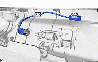
18. REMOVE REAR NO. 1 POWER OUTLET SOCKET ASSEMBLY
| (a) Disengage the 2 clamps. |
|
(b) Using a screwdriver with its tip wrapped with protective tape, disengage the claw and remove the rear No. 1 power outlet socket assembly as shown in the illustration.
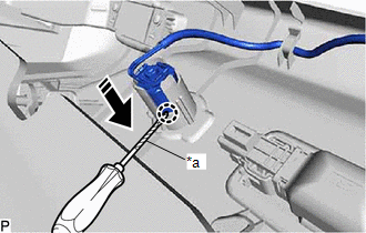
| *a | Protective Tape |
.png) | Remove in this Direction |
(c) Using a screwdriver, disengage the claw and remove the clamp from the rear No. 1 power outlet socket assembly as shown in the illustration.
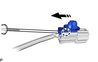
| | Remove in this Direction |
19. REMOVE REAR POWER OUTLET SOCKET COVER
(a) Disengage the 2 claws and remove the rear power outlet socket cover as shown in the illustration.
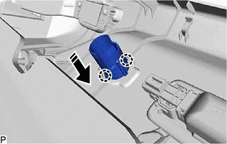
| | Remove in this Direction |
 Components
COMPONENTS ILLUSTRATION *A except TMMC Made *B for TMMC Made *1 DECK BOARD ASSEMBLY *2 DECK SIDE TRIM BOX RH *3 FRONT DECK FLOOR BOX *4 REAR DECK FLOOR BOX *5 REAR ...
 Installation
INSTALLATION PROCEDURE 1. INSTALL REAR POWER OUTLET SOCKET COVER (a) Engage the 2 claws to install the rear power outlet socket cover as shown in the illustration. Install in this Direction ...
Other materials:
Lexus RX (RX 350L, RX450h) 2016-2026 Repair Manual > Power Back Door System (w/ Outside Door Control Switch): Power Back Door does not Operate Using Outside Switch
DESCRIPTION The multiplex network door ECU detects the status of the power back door control switch. If the power back door does not operate when the power back door control switch is operated, there may be a malfunction in the power back door control switch circuit. WIRING DIAGRAM CAUTION / NOTICE ...
Lexus RX (RX 350L, RX450h) 2016-2026 Repair Manual > Steering System: Precaution
PRECAUTION HANDLING PRECAUTIONS FOR STEERING SYSTEM (a) Care must be taken when replacing parts. Incorrect replacement may affect the performance of the steering system and result in a driving hazard. HANDLING PRECAUTIONS FOR SRS AIRBAG SYSTEM (a) This vehicle is equipped with a Supplemental Restrai ...
Lexus RX (RX 350L, RX450h) 2016-{YEAR} Owners Manual
- For your information
- Pictorial index
- For safety and security
- Instrument cluster
- Operation of each component
- Driving
- Lexus Display Audio system
- Interior features
- Maintenance and care
- When trouble arises
- Vehicle specifications
- For owners
Lexus RX (RX 350L, RX450h) 2016-{YEAR} Repair Manual

0.0096