Lexus RX (RX 350L, RX450h) 2016-2026 Repair Manual: Power Back Door does not Operate Using Outside Switch
DESCRIPTION
The multiplex network door ECU detects the status of the power back door control switch.
If the power back door does not operate when the power back door control switch is operated, there may be a malfunction in the power back door control switch circuit.
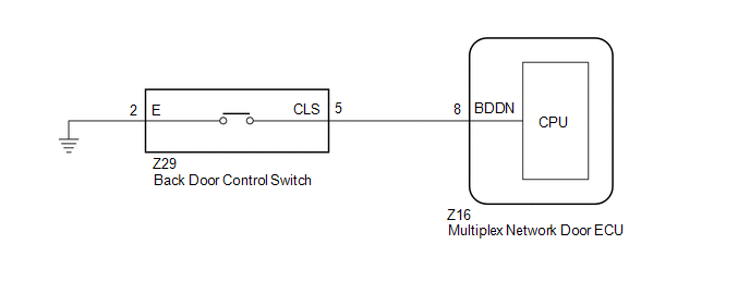
WIRING DIAGRAM
CAUTION / NOTICE / HINT
NOTICE:
If the replacement, removal and installation of the multiplex network door ECU or disconnection of the connectors of the multiplex network door ECU has been performed, initialize the power back door system.
Click here .gif)
PROCEDURE
| 1. | READ VALUE USING TECHSTREAM |
(a) Connect the Techstream to the DLC3.
(b) Turn the engine switch on (IG).
(c) Turn the Techstream on.
(d) Enter the following menus: Body Electrical / Master Switch / Data List.
(e) Read the Data List according to the display on the Techstream.
Body Electrical > Back Door > Data List| Tester Display | Measurement Item | Range | Normal Condition | Diagnostic Note |
|---|---|---|---|---|
| PBD Close SW | Back door control switch signal | OFF or ON | OFF: Back door control switch not pressed ON: Back door control switch pressed | - |
| Tester Display |
|---|
| PBD Close SW |
OK:
The display is as specified in the normal condition column.
| OK | .gif) | REPLACE MULTIPLEX NETWORK DOOR ECU |
|
.gif)
| 2. | INSPECT BACK DOOR CONTROL SWITCH |
(a) Remove the back door control switch.
Click here
(b) Inspect the back door control switch.
Click here
| NG | | REPLACE BACK DOOR CONTROL SWITCH |
|
| 3. | CHECK HARNESS AND CONNECTOR (BACK DOOR CONTROL SWITCH - MULTIPLEX NETWORK DOOR ECU AND BODY GROUND) |
(a) Disconnect the Z16 multiplex network door ECU connector.
(b) Measure the resistance according to the value(s) in the table below.
Standard Resistance:
| Tester Connection | Condition | Specified Condition |
|---|---|---|
| Z29-5 (CLS) - Z16-8 (BDDN) | Always | Below 1 Ω |
| Z29-2 (E) - Body ground | Always | Below 1 Ω |
| Z29-5 (CLS) or Z16-8 (BDDN) - Body ground | Always | 10 kΩ or higher |
| OK | | REPLACE MULTIPLEX NETWORK DOOR ECU |
| NG | | REPAIR OR REPLACE HARNESS OR CONNECTOR |
 Power Back Door does not Operate Using Cabin Switch
DESCRIPTION The power back door switch (integration control and panel assembly) signal is sent to the multiplex network door ECU via CAN communication. If the power back door does not operate when the ...
 Power Back Door Warning System does not Operate
DESCRIPTION If the power back door warning system does not operate, there may be a malfunction in one of the following: 1) wireless door lock control system, 2) power back door warning buzzer circuit ...
Other materials:
Lexus RX (RX 350L, RX450h) 2016-2026 Repair Manual > Fuel Pump (for High Pressure): Components
COMPONENTS ILLUSTRATION *A for TMC Made *B for TMMC Made *1 NO. 2 ENGINE UNDER COVER - - ILLUSTRATION *1 FUEL PUMP ASSEMBLY *2 FUEL PUMP PROTECTOR *3 NO. 1 FUEL PIPE SUB-ASSEMBLY *4 NO. 2 FUEL TUBE SUB-ASSEMBLY *5 FUEL PUMP LIFTER ASSEMBLY *6 FUEL ...
Lexus RX (RX 350L, RX450h) 2016-2026 Repair Manual > Can Communication System: Check Bus 4 Line for Short to GND
DESCRIPTION There may be a short circuit between one of the CAN bus lines and GND when there is no resistance between terminal 22 (CA2H) of the network gateway ECU and terminal 4 (CG) of the DLC3, or terminal 7 (CA2L) of the network gateway ECU and terminal 4 (CG) of the DLC3. Symptom Trouble A ...
Lexus RX (RX 350L, RX450h) 2016-{YEAR} Owners Manual
- For your information
- Pictorial index
- For safety and security
- Instrument cluster
- Operation of each component
- Driving
- Lexus Display Audio system
- Interior features
- Maintenance and care
- When trouble arises
- Vehicle specifications
- For owners
Lexus RX (RX 350L, RX450h) 2016-{YEAR} Repair Manual

0.0094