Lexus RX (RX 350L, RX450h) 2016-2026 Repair Manual: IG Power Supply Voltage (C1551)
DESCRIPTION
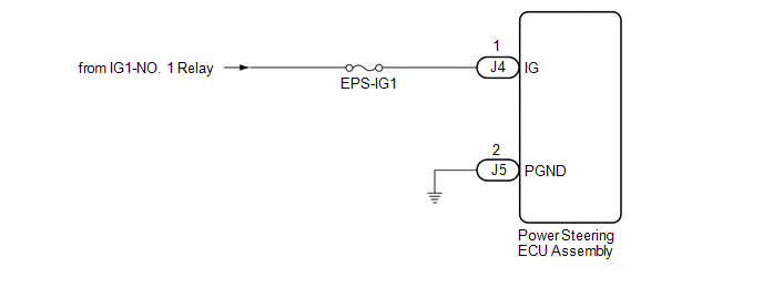
The power steering ECU assembly distinguishes the engine switch status as on (IG) or off through the IG power source circuit.
| DTC No. | Detection Item | DTC Detection Condition | Trouble Area | Warning Indicate | Return-to-normal Condition | Note |
|---|---|---|---|---|---|---|
| C1551 | IG Power Supply Voltage | Open or short in IG power source circuit with engine switch on (IG) |
| EPS warning light: Comes on | The ECU judges the system has returned to normal or the power switch is turned on (IG) again | - |
WIRING DIAGRAM
CAUTION / NOTICE / HINT
NOTICE:
-
If the power steering ECU assembly has been replaced, perform assist map writing and torque sensor zero point calibration.
Click here
.gif)
- Inspect the fuses for circuits related to this system before performing the following procedure.
PROCEDURE
| 1. | CHECK HARNESS AND CONNECTOR (BATTERY - POWER STEERING ECU ASSEMBLY) |
(a) Disconnect the J5 and J4 power steering ECU assembly connectors.
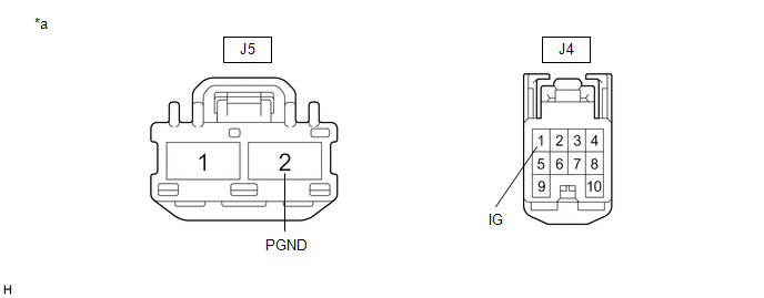
| *a | Front view of wire harness connector (to Power Steering ECU Assembly) | - | - |
(b) Measure the voltage according to the value(s) in the table below.
Standard Voltage:
| Tester Connection | Condition | Specified Condition |
|---|---|---|
| J4-1 (IG) - Body ground | Engine switch on (IG) | 8 to 16 V |
(c) Measure the resistance according to the value(s) in the table below.
Standard Resistance:
| Tester Connection | Condition | Specified Condition |
|---|---|---|
| J5-2 (PGND) - Body ground | Always | Below 1 Ω |
| OK | .gif) | REPLACE POWER STEERING ECU ASSEMBLY |
| NG | | REPAIR OR REPLACE HARNESS OR CONNECTOR |
 Vehicle Speed Signal (C1541)
DESCRIPTION The power steering ECU assembly receives vehicle speed signals from the skid control ECU (brake actuator assembly) via CAN communication. The ECU provides appropriate assist force in accor ...
 PIG Power Supply Voltage (C1552,C1554)
DESCRIPTION If a problem occurs in the system, the power source relay circuit and the motor relay circuit are shut off to stop power assist. The ECU must be replaced when there is a problem with the r ...
Other materials:
Lexus RX (RX 350L, RX450h) 2016-2026 Repair Manual > Panoramic Moon Roof System: Position Initialization Incomplete (B2343)
DESCRIPTION This DTC is stored when the sliding roof ECU (sliding roof drive gear assembly) or roof sunshade ECU (sliding roof drive gear assembly) has not been initialized. Sliding Roof DTC No. Detection Item DTC Detection Condition Trouble Area B2343 Position Initialization Incomple ...
Lexus RX (RX 350L, RX450h) 2016-2026 Owners Manual > Do-it-yourself
maintenance: Windshield wiper inserts
Replacing a windshield wiper insert
1. Change the rest position of the windshield wipers to the service position
using
the wiper lever and then lift a windshield wiper.
2. While pressing and holding the
wiper blade lock release button,
remove the wiper blade.
When performing this operation ...
Lexus RX (RX 350L, RX450h) 2016-{YEAR} Owners Manual
- For your information
- Pictorial index
- For safety and security
- Instrument cluster
- Operation of each component
- Driving
- Lexus Display Audio system
- Interior features
- Maintenance and care
- When trouble arises
- Vehicle specifications
- For owners
Lexus RX (RX 350L, RX450h) 2016-{YEAR} Repair Manual

0.009