Lexus RX (RX 350L, RX450h) 2016-2026 Repair Manual: PIG Power Supply Voltage (C1552,C1554)
DESCRIPTION
If a problem occurs in the system, the power source relay circuit and the motor relay circuit are shut off to stop power assist. The ECU must be replaced when there is a problem with the relays because the relays are built into the ECU.
| DTC No. | Detection Item | DTC Detection Condition | Trouble Area | Warning Indicate | Return-to-normal Condition | Note |
|---|---|---|---|---|---|---|
| C1552 | PIG Power Supply Voltage | PIG power source circuit malfunction |
| EPS warning light: Comes on | Engine switch on (IG) again | - |
| C1554 | Power Supply Relay Failure | Power source relay circuit malfunction |
| EPS warning light: Comes on | Engine switch on (IG) again | - |
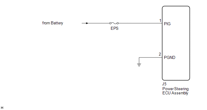
WIRING DIAGRAM
CAUTION / NOTICE / HINT
NOTICE:
-
If the power steering ECU assembly has been replaced, perform assist map writing and torque sensor zero point calibration.
Click here
.gif)
- Inspect the fuses for circuits related to this system before performing the following procedure.
PROCEDURE
| 1. | CHECK HARNESS AND CONNECTOR (POWER STEERING ECU ASSEMBLY - BODY GROUND) |
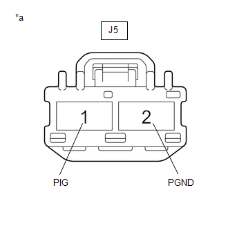
(a) Disconnect the J5 power steering ECU assembly connectors.
(b) Measure the voltage according to the value(s) in the table below.
Standard Voltage:
| Tester Connection | Condition | Specified Condition |
|---|---|---|
| J5-1 (PIG) - Body ground | Engine switch on (IG) | 9 to 16 V |
| (c) Measure the resistance according to the value(s) in the table below. Standard Resistance:
|
|
| OK | .gif) | REPLACE POWER STEERING ECU ASSEMBLY |
| NG | | REPAIR OR REPLACE HARNESS OR CONNECTOR |
 IG Power Supply Voltage (C1551)
DESCRIPTION The power steering ECU assembly distinguishes the engine switch status as on (IG) or off through the IG power source circuit. DTC No. Detection Item DTC Detection Condition Troubl ...
 Error in Matching of ECUs (C1567)
DESCRIPTION Based on the steering sensor signal, the power steering ECU assembly determines if the correct type of steering sensor is installed. DTC No. Detection Item DTC Detection Condition ...
Other materials:
Lexus RX (RX 350L, RX450h) 2016-2026 Repair Manual > Parking Assist Monitor System: Steering Angle Initialization Incomplete (C1694)
DESCRIPTION This DTC is stored when the rear television camera assembly judges that the maximum steering angle has not been memorized (steering angle setting is incomplete). DTC No. Detection Item DTC Detection Condition Trouble Area C1694 Steering Angle Initialization Incomplete Ma ...
Lexus RX (RX 350L, RX450h) 2016-2026 Repair Manual > Rear Seatback Heater (for Captain Seat Type): Components
COMPONENTS ILLUSTRATION *1 CUP HOLDER ASSEMBLY *2 NO. 1 RECLINING ADJUSTER RELEASE HANDLE LH *3 NO. 1 SEAT ARMREST CAP *4 REAR SEAT ARMREST ASSEMBLY LH *5 REAR SEAT COVER CAP LH *6 REAR SEAT INNER RECLINING COVER LH *7 REAR SEAT LOCK CONTROL LEVER SUB-ASSEMBLY LH ...
Lexus RX (RX 350L, RX450h) 2016-{YEAR} Owners Manual
- For your information
- Pictorial index
- For safety and security
- Instrument cluster
- Operation of each component
- Driving
- Lexus Display Audio system
- Interior features
- Maintenance and care
- When trouble arises
- Vehicle specifications
- For owners
Lexus RX (RX 350L, RX450h) 2016-{YEAR} Repair Manual

0.0099