Lexus RX (RX 350L, RX450h) 2016-2026 Repair Manual: Power Back Door Warning System does not Operate
DESCRIPTION
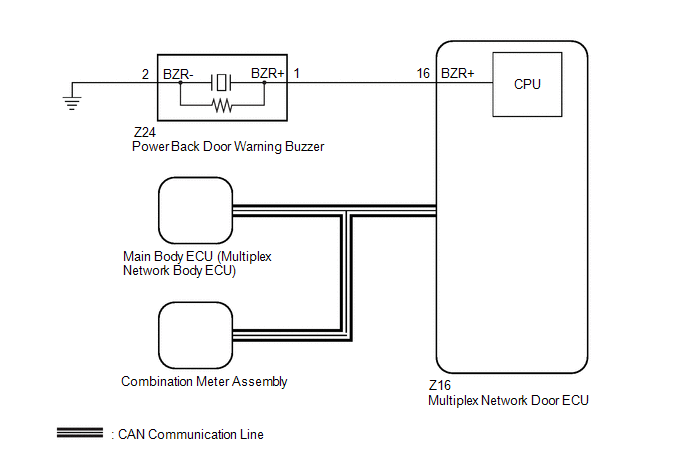
If the power back door warning system does not operate, there may be a malfunction in one of the following: 1) wireless door lock control system, 2) power back door warning buzzer circuit or 3) multiplex network door ECU.
WIRING DIAGRAM
CAUTION / NOTICE / HINT
NOTICE:
-
If the multiplex network door ECU has been removed and installed or replaced, or if any of the connectors have been disconnected, initialize the power back door system.
Click here
.gif)
-
The PBD Buzzer can be customized. Make sure the function is set to ON.
Click here
-
If the main body ECU (multiplex network body ECU) is replaced, refer to Registration.
Click here
PROCEDURE
| 1. | CHECK OPERATION |
(a) Check power back door system operation.
Click here
| Result | Proceed to |
|---|---|
| Hazard warning light does not come on (w/ Power Back Door Hazard Warning Light) | A |
| Power back door warning buzzer does not operate | B |
| B | .gif) | GO TO STEP 6 |
|
.gif)
| 2. | CHECK WIRELESS DOOR LOCK CONTROL SYSTEM (HAZARD ANSWER-BACK FUNCTION) |
(a) Check wireless door lock operation.
Click here
OK:
Hazard answer-back function operates normally.
| NG | | GO TO WIRELESS DOOR LOCK CONTROL SYSTEM |
|
| 3. | REPLACE MULTIPLEX NETWORK DOOR ECU |
(a) Temporarily replace the multiplex network door ECU with a new or known good one.
Click here
|
| 4. | INITIALIZE POWER BACK DOOR SYSTEM |
(a) Perform initialize the power back door system.
Click here
|
| 5. | CHECK POWER BACK DOOR SYSTEM |
(a) Check that the power back door hazard warning lights operate normally.
Click here
OK:
The power back door hazard warning lights operate normally.
| OK | | END (MULTIPLEX NETWORK DOOR ECU WAS DEFECTIVE) |
| NG | | REPLACE MAIN BODY ECU (MULTIPLEX NETWORK BODY ECU) |
| 6. | PERFORM ACTIVE TEST USING TECHSTREAM (PBD BUZZER) |
(a) Connect the Techstream to the DLC3.
(b) Turn the engine switch on (IG).
(c) Turn the Techstream on.
(d) Enter the following menus: Body Electrical / Back Door / Data List.
(e) Perform the Active Test according to the display on the Techstream.
Body Electrical > Back Door > Active Test| Tester Display | Measurement Item | Control Range | Diagnostic Note |
|---|---|---|---|
| PBD Buzzer | Power back door warning buzzer sound | OFF or ON | - |
| Tester Display |
|---|
| PBD Buzzer |
OK:
Power back door warning buzzer sounds
| OK | | REPLACE MULTIPLEX NETWORK DOOR ECU |
|
| 7. | CHECK HARNESS AND CONNECTOR (POWER BACK DOOR WARNING BUZZER - MULTIPLEX NETWORK DOOR ECU AND BODY GROUND) |
(a) Disconnect the Z24 power back door warning buzzer connector.
(b) Disconnect the Z16 multiplex network door ECU connector.
(c) Measure the resistance according to the value(s) in the table below.
Standard Resistance:
| Tester Connection | Condition | Specified Condition |
|---|---|---|
| Z24-1 (BZR+) - Z16-16 (BZR+) | Always | Below 1 Ω |
| Z24-2 (BZR-) - Body ground | Always | Below 1 Ω |
| Z24-1 (BZR+) or Z16-16 (BZR+) - Body ground | Always | 10 kΩ or higher |
| NG | | REPAIR OR REPLACE HARNESS OR CONNECTOR |
|
| 8. | REPLACE POWER BACK DOOR WARNING BUZZER |
(a) Replace the power back door warning buzzer with a new or known good one.
Click here
|
| 9. | CHECK POWER BACK DOOR WARNING SYSTEM |
(a) Check that the power back door warning buzzer operates normally.
Click here
OK:
Power back door warning buzzer sounds
| OK | | END (POWER BACK DOOR WARNING BUZZER WAS MALFUNCTIONING) |
| NG | | REPLACE MULTIPLEX NETWORK DOOR ECU |
 Power Back Door does not Operate Using Outside Switch
DESCRIPTION The multiplex network door ECU detects the status of the power back door control switch. If the power back door does not operate when the power back door control switch is operated, there ...
 Jam Protection Function Activates During Power Back Door Operation
DESCRIPTION If the jam protection function activates during power back door operation, one of the following may be the cause: 1) improper fit of back door or a foreign object stuck in the back door, 2 ...
Other materials:
Lexus RX (RX 350L, RX450h) 2016-2026 Repair Manual > Rear No. 1 Seat Assembly (for 60/40 Split Seat Type Lh Side): Reassembly
REASSEMBLY CAUTION / NOTICE / HINT CAUTION: Wear protective gloves. Sharp areas on the seat frame may injure your hands. PROCEDURE 1. INSTALL REAR SEATBACK FRAME SUB-ASSEMBLY LH (a) Temporarily install the rear seatback frame sub-assembly LH to the No. 1 seat cushion frame sub-assembly LH as shown i ...
Lexus RX (RX 350L, RX450h) 2016-2026 Repair Manual > Vehicle Stability Control System: ABS Pump Motor Control Circuit Open (C052C13,C052C49,C052F14)
DESCRIPTION The motor relay and motor fail safe relay are built into the brake actuator assembly. When the skid control ECU (brake actuator assembly) operate ABS, TRAC, VSC, brake hold or brake assist, the motor relay turns ON and drives the motor pump built into the brake actuator assembly. If any ...
Lexus RX (RX 350L, RX450h) 2016-{YEAR} Owners Manual
- For your information
- Pictorial index
- For safety and security
- Instrument cluster
- Operation of each component
- Driving
- Lexus Display Audio system
- Interior features
- Maintenance and care
- When trouble arises
- Vehicle specifications
- For owners
Lexus RX (RX 350L, RX450h) 2016-{YEAR} Repair Manual

0.0133