Lexus RX (RX 350L, RX450h) 2016-2026 Repair Manual: Power Back Door does not Operate Using Cabin Switch
DESCRIPTION
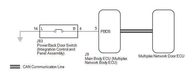
The power back door switch (integration control and panel assembly) signal is sent to the multiplex network door ECU via CAN communication.
If the power back door does not operate when the power back door switch (integration control and panel assembly) is operated, there may be a malfunction in the power back door switch (integration control and panel assembly) circuit.
WIRING DIAGRAM
CAUTION / NOTICE / HINT
NOTICE:
-
The power back door system uses the CAN communication system. Inspect the communication function by following How to Proceed with Troubleshooting. Troubleshoot the power back door system after confirming that the CAN communication system is functioning properly.
Click here
.gif)
-
If the replacement, removal and installation of the multiplex network door ECU or disconnection of the connectors of the multiplex network door ECU has been performed, initialize the power back door system.
Click here
-
If the main body ECU (multiplex network body ECU) is replaced, refer to Registration.
Click here
PROCEDURE
| 1. | READ VALUE USING TECHSTREAM |
(a) Connect the Techstream to the DLC3.
(b) Turn the engine switch on (IG).
(c) Turn the Techstream on.
(d) Enter the following menus: Body Electrical / Main Body / Data List.
(e) Read the Data List according to the display on the Techstream.
Body Electrical > Main Body > Data List| Tester Display | Measurement Item | Range | Normal Condition | Diagnostic Note |
|---|---|---|---|---|
| Back Door Open SW | Power back door switch (integration control and panel assembly) signal | OFF or ON | OFF: Power back door switch (integration control and panel assembly) off ON: Power back door switch (integration control and panel assembly) on | - |
| Tester Display |
|---|
| Back Door Open SW |
OK:
The display is as specified in the normal condition column.
| OK | .gif) | REPLACE MULTIPLEX NETWORK DOOR ECU |
|
.gif)
| 2. | INSPECT POWER BACK DOOR SWITCH (INTEGRATION CONTROL AND PANEL ASSEMBLY) |
(a) Remove the power back door switch (integration control and panel assembly).
Click here
(b) Inspect the power back door switch (integration control and panel assembly).
Click here
| NG | | REPLACE POWER BACK DOOR SWITCH (INTEGRATION CONTROL AND PANEL ASSEMBLY) |
|
| 3. | CHECK HARNESS AND CONNECTOR (INTEGRATION CONTROL AND PANEL ASSEMBLY - MAIN BODY ECU (MULTIPLAX NETWORK BODY ECU)) |
(a) Disconnect the J9 main body ECU (multiplex network body ECU) connector.
(b) Measure the resistance according to the value(s) in the table below.
Standard Resistance:
| Tester Connection | Condition | Specified Condition |
|---|---|---|
| J83-4 (B) - J9-5 (PBDS) | Always | Below 1 Ω |
| J83-14 (L) - Body ground | Always | Below 1 Ω |
| J83-4 (B) or J9-5 (PBDS) - Body ground | Always | 10 kΩ or higher |
| OK | | REPLACE MAIN BODY ECU (MULTIPLEX NETWORK BODY ECU) |
| NG | | REPAIR OR REPLACE HARNESS OR CONNECTOR |
 Power Back Door cannot be Operated Using Any Switch
DESCRIPTION If the power back door system cannot be operated using any switch, the multiplex network door ECU may not have been initialized, or there may be a malfunction in the power back door sensor ...
 Power Back Door does not Operate Using Outside Switch
DESCRIPTION The multiplex network door ECU detects the status of the power back door control switch. If the power back door does not operate when the power back door control switch is operated, there ...
Other materials:
Lexus RX (RX 350L, RX450h) 2016-2026 Repair Manual > Sliding Roof System: Sliding Roof does not Move by Operating Sliding Roof Control Switch
DESCRIPTION The sliding roof ECU (sliding roof drive gear sub-assembly) receives slide and tilt signals and operates its built-in motor when the sliding roof switch (map light assembly) is operated. WIRING DIAGRAM Click here CAUTION / NOTICE / HINT NOTICE:
Inspect the fuses for circuits related ...
Lexus RX (RX 350L, RX450h) 2016-2026 Repair Manual > Power Steering System: On-vehicle Inspection
ON-VEHICLE INSPECTION PROCEDURE 1. CHECK STEERING EFFORT (TORQUE) NOTICE: These service operations may affect the SRS airbags. Be sure to read the precautionary notices concerning the SRS airbag system before servicing. Click here (a) Stop the vehicle on a level, paved surface and align the whe ...
Lexus RX (RX 350L, RX450h) 2016-{YEAR} Owners Manual
- For your information
- Pictorial index
- For safety and security
- Instrument cluster
- Operation of each component
- Driving
- Lexus Display Audio system
- Interior features
- Maintenance and care
- When trouble arises
- Vehicle specifications
- For owners
Lexus RX (RX 350L, RX450h) 2016-{YEAR} Repair Manual

0.0109