Lexus RX (RX 350L, RX450h) 2016-2026 Repair Manual: Power Back Door cannot be Operated Using Any Switch
DESCRIPTION
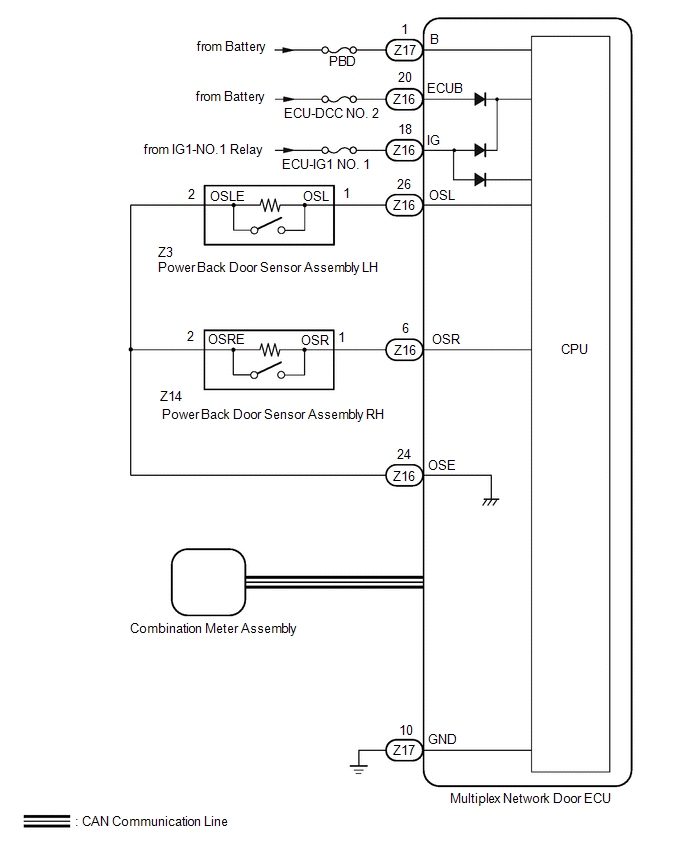
If the power back door system cannot be operated using any switch, the multiplex network door ECU may not have been initialized, or there may be a malfunction in the power back door sensor assembly circuit, CAN communication system, back door closer, meter/gauge system, multiplex network door ECU power source circuit, or multiplex network door ECU.
WIRING DIAGRAM
CAUTION / NOTICE / HINT
NOTICE:
-
The power back door system uses the CAN communication system. Inspect the communication function by following How to Proceed with Troubleshooting. Troubleshoot the power back door system after confirming that the CAN communication system is functioning properly.
Click here
.gif)
- Inspect the fuses for circuits related to this system before performing the following procedure.
-
If the multiplex network door ECU has been removed and installed or replaced, or if any of the connectors have been disconnected, initialize the power back door system.
Click here
- If the 2-step unlock function is enabled via customize settings, only the driver door unlocks when the first unlock operation is performed and the power back door does not operate as all the doors are not unlocked.
PROCEDURE
| 1. | CHECK CUSTOMIZE SETTING |
(a) Read the customize setting "Unlock Key Twice" according to the display on the GTS.
Click here
| Result | Proceed to |
|---|---|
| The customize setting is "OFF" | A |
| The customize setting is "ON" | B |
| B | .gif) | PERFORM CUSTOMIZE SETTING |
|
.gif)
| 2. | CHECK CUSTOMIZE SETTING |
(a) Read the customize setting "Unlock 2 Operation" according to the display on the GTS.
Click here
| Result | Proceed to |
|---|---|
| The customize setting is "OFF" | A |
| The customize setting is "ON" | B |
| B | | PERFORM CUSTOMIZE SETTING |
|
| 3. | CHECK COMBINATION METER ASSEMBLY |
(a) Check that the shift position indicator operates correctly and the speedometer indicates 0 km/h (0 mph) when the vehicle is stopped with the engine was running.
OK:
Combination meter operates normally
| NG | | GO TO METER / GAUGE SYSTEM |
|
| 4. | CHECK FOR DTC |
(a) Connect the Techstream to the DLC3.
(b) Turn the engine switch on (IG).
(c) Turn the Techstream on.
(d) Enter the following menus: Body Electrical / Back Door / Trouble Codes.
(e) Check for DTCs.
Body Electrical > Back Door > Trouble CodesOK:
DTC is not output
| NG | | GO TO DIAGNOSTIC TROUBLE CODE CHART |
|
| 5. | CHECK HARNESS AND CONNECTOR (MULTIPLEX NETWORK DOOR ECU - BATTERY AND BODY GROUND) |
| (a) Measure the resistance according to the value(s) in the table below. Standard Resistance:
|
|
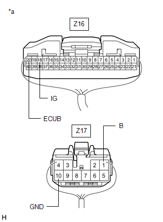
(b) Measure the voltage according to the value(s) in the table below.
Standard Voltage:
| Tester Connection | Condition | Specified Condition |
|---|---|---|
| Z16-20 (ECUB) - Body ground | Always | 11 to 14 V |
| Z17-1 (B) - Body ground | Always | 11 to 14 V |
| Z16-18 (IG) - Body ground | Engine switch on (IG) | 11 to 14 V |
| Engine switch off | Below 1 V |
| NG | | REPAIR OR REPLACE HARNESS OR CONNECTOR |
|
| 6. | READ VALUE USING TECHSTREAM (PBD MAIN SW) |
(a) Connect the Techstream to the DLC3.
(b) Turn the engine switch on (IG).
(c) Turn the Techstream on.
(d) Enter the following menus: Body Electrical / Back Door / Data List.
(e) Read the Data List according to the display on the Techstream.
Body Electrical > Back Door > Data List| Tester Display | Measurement Item | Range | Normal Condition | Diagnostic Note |
|---|---|---|---|---|
| PBD Main SW | Power back door ON/OFF signal | OFF or ON | Customize setting displayed | - |
| Tester Display |
|---|
| PBD Main SW |
OK:
The display is as specified in the normal condition column.
| NG | | GO TO METER / GAUGE SYSTEM |
|
| 7. | READ VALUE USING TECHSTREAM (PBD TOUCH SENSOR) |
(a) Enter the following menus: Body Electrical / Back Door / Data List.
(b) Read the Data List according to the display on the Techstream.
Body Electrical > Back Door > Data List| Tester Display | Measurement Item | Range | Normal Condition | Diagnostic Note |
|---|---|---|---|---|
| PBD Touch Sensor (Right) | Power back door sensor assembly RH signal | OFF, ON or Open | OFF: Power back door sensor assembly RH not pressed ON: Power back door sensor assembly RH pressed Open: Power back door sensor assembly RH circuit open | - |
| PBD Touch Sensor (Left) | Power back door sensor assembly LH signal | OFF, ON or Open | OFF: Power back door sensor assembly LH not pressed ON: Power back door sensor assembly LH pressed Open: Power back door sensor assembly LH circuit open | - |
| Tester Display |
|---|
| PBD Touch Sensor (Right) |
| PBD Touch Sensor (Left) |
| Result | Proceed to |
|---|---|
| The values of Data List items "PBD Touch Sensor (Right)" and "PBD Touch Sensor (Left)" change to "ON" or "OFF" in accordance with the operation of the sensors. | A |
| The value of Data List item "PBD Touch Sensor (Right)" does not change to "ON" or "OFF" in accordance with the operation of the power back door sensor assembly RH. | B |
| The value of Data List item "PBD Touch Sensor (Left)" does not change to "ON" or "OFF" in accordance with the operation of the power back door sensor assembly LH. | C |
| A | | REPLACE MULTIPLEX NETWORK DOOR ECU |
| C | | GO TO STEP 10 |
|
| 8. | INSPECT POWER BACK DOOR SENSOR ASSEMBLY RH |
(a) Remove the power back door sensor assembly RH.
Click here
(b) Inspect the power back door sensor assembly RH.
Click here
| NG | | REPLACE POWER BACK DOOR SENSOR ASSEMBLY RH |
|
| 9. | CHECK HARNESS AND CONNECTOR (POWER BACK DOOR SENSOR ASSEMBLY RH - MULTIPLEX NETWORK DOOR ECU) |
(a) Disconnect the Z16 multiplex network door ECU connector.
(b) Measure the resistance according to the value(s) in the table below.
Standard Resistance:
| Tester Connection | Condition | Specified Condition |
|---|---|---|
| Z14-1 (OSR) - Z16-6 (OSR) | Always | Below 1 Ω |
| Z14-2 (OSRE) - Z16-24 (OSE) | Always | Below 1 Ω |
| Z14-1 (OSR) or Z16-6 (OSR) - Body ground | Always | 10 kΩ or higher |
| Z14-2 (OSRE) or Z16-24 (OSE) - Body ground | Always | 10 kΩ or higher |
| OK | | REPLACE MULTIPLEX NETWORK DOOR ECU |
| NG | | REPAIR OR REPLACE HARNESS OR CONNECTOR |
| 10. | INSPECT POWER BACK DOOR SENSOR ASSEMBLY LH |
(a) Remove the power back door sensor assembly LH.
Click here
(b) Inspect the power back door sensor assembly LH.
Click here
| NG | | REPLACE POWER BACK DOOR SENSOR ASSEMBLY LH |
|
| 11. | CHECK HARNESS AND CONNECTOR (POWER BACK DOOR SENSOR ASSEMBLY LH - MULTIPLEX NETWORK DOOR ECU) |
(a) Disconnect the Z16 multiplex network door ECU connector.
(b) Measure the resistance according to the value(s) in the table below.
Standard Resistance:
| Tester Connection | Condition | Specified Condition |
|---|---|---|
| Z3-1 (OSL) - Z16-26 (OSL) | Always | Below 1 Ω |
| Z3-2 (OSLE) - Z16-24 (OSE) | Always | Below 1 Ω |
| Z3-1 (OSL) or Z16-26 (OSL) - Body ground | Always | 10 kΩ or higher |
| Z3-2 (OSLE) or Z16-24 (OSE) - Body ground | Always | 10 kΩ or higher |
| OK | | REPLACE MULTIPLEX NETWORK DOOR ECU |
| NG | | REPAIR OR REPLACE HARNESS OR CONNECTOR |
 Back Door Closer does not Operate
DESCRIPTION If the back door closer does not operate, one of the following may be the cause: 1) improper fit of the back door or a foreign object stuck in the back door, 2) a malfunction in the multip ...
 Power Back Door does not Operate Using Cabin Switch
DESCRIPTION The power back door switch (integration control and panel assembly) signal is sent to the multiplex network door ECU via CAN communication. If the power back door does not operate when the ...
Other materials:
Lexus RX (RX 350L, RX450h) 2016-2026 Repair Manual > Steering Column Assembly: Inspection
INSPECTION PROCEDURE 1. INSPECT PRELOAD (a) Secure the steering column assembly in a vise using aluminum plates, cloths and wooden blocks. NOTICE:
Do not overtighten the vise, as the steering column assembly may become deformed.
Support the steering column assembly with wooden blocks or si ...
Lexus RX (RX 350L, RX450h) 2016-2026 Repair Manual > Vehicle Stability Control System: Excessive Brake Pedal Travel (No Fluid Leaks and No Air in System)
CAUTION / NOTICE / HINT NOTICE: After replacing the skid control ECU (brake actuator assembly), perform "Calibration". Click here PROCEDURE 1. PRE-INSPECTION (a) Brake pedal inspection (1) Perform a visual inspection and operate the brake pedal to check for any malfunctions. (2) Check the ...
Lexus RX (RX 350L, RX450h) 2016-{YEAR} Owners Manual
- For your information
- Pictorial index
- For safety and security
- Instrument cluster
- Operation of each component
- Driving
- Lexus Display Audio system
- Interior features
- Maintenance and care
- When trouble arises
- Vehicle specifications
- For owners
Lexus RX (RX 350L, RX450h) 2016-{YEAR} Repair Manual

0.01