Lexus RX (RX 350L, RX450h) 2016-2026 Repair Manual: Back Door Closer does not Operate
DESCRIPTION
If the back door closer does not operate, one of the following may be the cause: 1) improper fit of the back door or a foreign object stuck in the back door, 2) a malfunction in the multiplex network door ECU power source circuit, 3) a malfunction in the back door lock assembly circuit, 4) initialization of the multiplex network door ECU has not been performed or 5) a multiplex network door ECU malfunction.
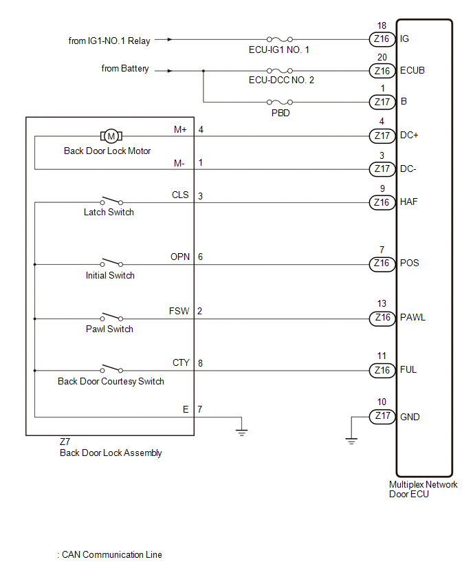
WIRING DIAGRAM
CAUTION / NOTICE / HINT
NOTICE:
- Inspect the fuses for circuits related to this system before performing the following procedure.
-
If the multiplex network door ECU has been removed and installed or replaced, or if any of the connectors have been disconnected, initialize the power back door system.
Click here
.gif)
PROCEDURE
| 1. | CHECK FOR DTC |
(a) Connect the Techstream to the DLC3.
(b) Turn the engine switch on (IG).
(c) Turn the Techstream on.
(d) Enter the following menus: Body Electrical / Back Door / Trouble Codes.
(e) Check for DTCs.
Body Electrical > Back Door > Trouble Codes| Result | Proceed to |
|---|---|
| DTC is not output | A |
| DTC B2250 is output | B |
| DTC B2251 is output | C |
| B | .gif) | GO TO DTC B2250 |
| C | | GO TO DTC B2251 |
|
.gif)
| 2. | CHECK BACK DOOR LOCK FUNCTION |
(a) Check if the back door can be fully closed by hand.
| Result | Proceed to |
|---|---|
| The back door can be closed normally | A |
| The back door cannot be closed normally | B |
| B | | IMPROPER FIT OF BACK DOOR, OR A FOREIGN OBJECT IS STUCK IN BACK DOOR |
|
| 3. | INITIALIZE POWER BACK DOOR SYSTEM |
(a) Perform initialize the power back door system.
Click here
|
| 4. | CHECK BACK DOOR CLOSER |
(a) When the back door is partially closed, check that the motor operates to fully close the back door.
| Result | Proceed to |
|---|---|
| The back door closer operates normally | A |
| The back door closer operates not normally | B |
| A | | END (BACK DOOR CLOSER HAS NOT BEEN INITIALIZED) |
|
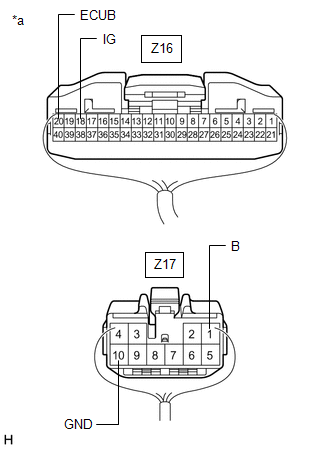
| 5. | CHECK HARNESS AND CONNECTOR (MULTIPLEX NETWORK DOOR ECU - BATTERY AND BODY GROUND) |
| (a) Measure the resistance according to the value(s) in the table below. Standard Resistance:
|
|
(b) Measure the voltage according to the value(s) in the table below.
Standard Voltage:
| Tester Connection | Condition | Specified Condition |
|---|---|---|
| Z16-20 (ECUB) - Body ground | Always | 11 to 14 V |
| Z17-1 (B) - Body ground | Always | 11 to 14 V |
| Z16-18 (IG) - Body ground | Engine switch on (IG) | 11 to 14 V |
| Engine switch off | Below 1 V |
| NG | | REPAIR OR REPLACE HARNESS OR CONNECTOR |
|
| 6. | INSPECT BACK DOOR LOCK ASSEMBLY |
(a) Remove the back door lock assembly.
Click here
(b) Inspect the back door lock assembly.
Click here
| NG | | REPLACE BACK DOOR LOCK ASSEMBLY |
|
| 7. | CHECK HARNESS AND CONNECTOR (BACK DOOR LOCK ASSEMBLY - MULTIPLEX NETWORK DOOR ECU AND BODY GROUND) |
(a) Disconnect the Z16 and Z17 multiplex network door ECU connectors.
(b) Measure the resistance according to the value(s) in the table below.
Standard Resistance:
| Tester Connection | Condition | Specified Condition |
|---|---|---|
| Z7-4 (M+) - Z17-4 (DC+) | Always | Below 1 Ω |
| Z7-1 (M-) - Z17-3 (DC-) | Always | Below 1 Ω |
| Z7-8 (CTY) - Z16-11 (FUL) | Always | Below 1 Ω |
| Z7-2 (FSW) - Z16-13 (PAWL) | Always | Below 1 Ω |
| Z7-3 (CLS) - Z16-9 (HAF) | Always | Below 1 Ω |
| Z7-6 (OPN) - Z16-7 (POS) | Always | Below 1 Ω |
| Z7-7 (E) - Body ground | Always | Below 1 Ω |
| Z7-4 (M+) or Z17-4 (DC+) - Body ground | Always | 10 kΩ or higher |
| Z7-1 (M-) or Z17-3 (DC-) - Body ground | Always | 10 kΩ or higher |
| Z7-8 (CTY) or Z16-11 (FUL) - Body ground | Always | 10 kΩ or higher |
| Z7-2 (FSW) or Z16-13 (PAWL) - Body ground | Always | 10 kΩ or higher |
| Z7-3 (CLS) or Z16-9 (HAF) - Body ground | Always | 10 kΩ or higher |
| Z7-6 (OPN) or Z16-7 (POS) - Body ground | Always | 10 kΩ or higher |
| OK | | REPLACE MULTIPLEX NETWORK DOOR ECU |
| NG | | REPAIR OR REPLACE HARNESS OR CONNECTOR |
 Lost Communication With TCM (U0101,U0122,U0142,U0155,U0327,U1117)
DESCRIPTION These DTCs are stored when a malfunction occurs in the CAN communication system. DTC No. Detection Item DTC Detection Condition Trouble Area U0101 Lost Communication With TC ...
 Power Back Door cannot be Operated Using Any Switch
DESCRIPTION If the power back door system cannot be operated using any switch, the multiplex network door ECU may not have been initialized, or there may be a malfunction in the power back door sensor ...
Other materials:
Lexus RX (RX 350L, RX450h) 2016-2026 Repair Manual > Window / Glass: Front Passenger Side Power Window Switch
ComponentsCOMPONENTS ILLUSTRATION *1 POWER WINDOW REGULATOR SWITCH ASSEMBLY *2 POWER WINDOW REGULATOR SWITCH ASSEMBLY WITH FRONT DOOR UPPER ARMREST BASE PANEL RemovalREMOVAL PROCEDURE 1. REMOVE POWER WINDOW REGULATOR SWITCH ASSEMBLY WITH FRONT DOOR UPPER ARMREST BASE PANEL Click here ...
Lexus RX (RX 350L, RX450h) 2016-2026 Repair Manual > Room Temperature Sensor (for Front): Components
COMPONENTS ILLUSTRATION *1 COOLER (ROOM TEMP. SENSOR) THERMISTOR *2 INSTRUMENT CLUSTER FINISH PANEL ORNAMENT *3 LOWER INSTRUMENT FINISH PANEL SUB *4 LOWER NO. 1 INSTRUMENT PANEL FINISH PANEL *5 LOWER NO. 2 INSTRUMENT PANEL FINISH PANEL - - ...
Lexus RX (RX 350L, RX450h) 2016-{YEAR} Owners Manual
- For your information
- Pictorial index
- For safety and security
- Instrument cluster
- Operation of each component
- Driving
- Lexus Display Audio system
- Interior features
- Maintenance and care
- When trouble arises
- Vehicle specifications
- For owners
Lexus RX (RX 350L, RX450h) 2016-{YEAR} Repair Manual

0.0107