Lexus RX (RX 350L, RX450h) 2016-2025 Repair Manual: Lost Communication with Cruise Control Front Distance Range Sensor Missing Message (U023587)
DESCRIPTION
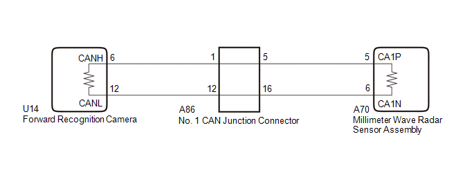
The forward recognition camera and millimeter wave radar sensor assembly communicate via CAN communication. If a signal is not received from the millimeter wave radar sensor assembly, the forward recognition camera stores a DTC.
| DTC No. | Detection Item | DTC Detection Condition | Trouble Area |
|---|---|---|---|
| U023587 | Lost Communication with Cruise Control Front Distance Range Sensor Missing Message | 3 seconds or more after the engine switch is turned on (IG), a communication malfunction with the millimeter wave radar sensor assembly is detected for 2 seconds or more. |
|
| Pattern | DTC Location Name (Techstream Displayed Name) | Suspected Area (Malfunction Status) | |
|---|---|---|---|
| Forward recognition camera (Pre-Collision System) | Millimeter wave radar sensor assembly (Front Radar Sensor) | ||
| U023587 | U010487 | ||
|
○: DTC is stored
-: DTC is not stored | |||
| Pattern 1 | ○ | ○ |
|
| Pattern 2 | ○ | - |
|
HINT:
If the DTCs are output simultaneously, the inspection area can be narrowed down.
WIRING DIAGRAM
CAUTION / NOTICE / HINT
NOTICE:
-
After turning the engine switch off, waiting time may be required before disconnecting the cable from the negative (-) battery terminal. Therefore, make sure to read the disconnecting the cable from the negative (-) battery terminal notices before proceeding with work.
Click here
.gif)
- When replacing the millimeter wave radar sensor assembly, always replace it with a new one. If a millimeter wave radar sensor assembly which was installed to another vehicle is used, the information stored in the millimeter wave radar sensor assembly will not match the information from the vehicle and a DTC may be stored.
-
When the millimeter wave radar sensor assembly has been replaced with a new one, it is necessary to perform millimeter wave radar sensor assembly adjustment and front radar acceleration sensor calibration, and to clear the vehicle control history.
Click here
- When replacing the forward recognition camera, always replace it with a new one. If a forward recognition camera which was installed to another vehicle is used, the information stored in the forward recognition camera will not match the information from the vehicle and a DTC may be stored.
-
If the forward recognition camera has been replaced with a new one, forward recognition camera adjustment must be performed.
HINT:
Forward recognition camera adjustment can be performed by using either One Time Recognition or Sequential Recognition.
One Time Recognition: Click here
Sequential Recognition: Click here
PROCEDURE
| 1. | CHECK FOR DTCs |
(a) Using the Techstream, check for front radar sensor system DTCs.
Body Electrical > Front Radar Sensor > Trouble Codes| Result | Proceed to |
|---|---|
| DTC U010487 is output | A |
| DTC U010487 is not output | B |
| B | .gif) | GO TO STEP 5 |
|
.gif)
| 2. | CHECK CAN BUS LINES (NO. 1 CAN JUNCTION CONNECTOR) |
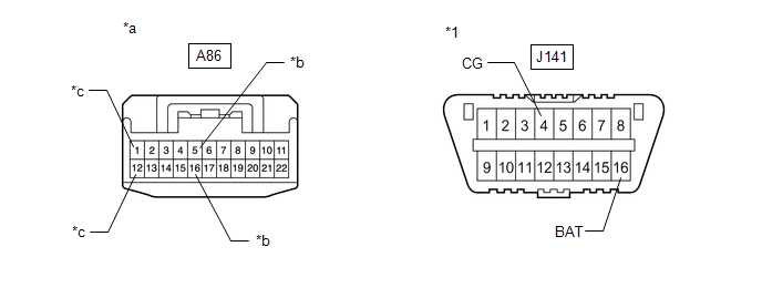
| *1 | DLC3 | - | - |
| *a | Front view of wire harness connector (to No. 1 CAN Junction Connector) | *b | to Millimeter Wave Radar Sensor Assembly |
| *c | to Forward Recognition Camera | - | - |
(a) Disconnect the cable from the negative (-) battery terminal.
(b) Disconnect the A86 No. 1 CAN junction connector.
(c) Measure the resistance according to the value(s) in the table below.
Standard Resistance:
| Tester Connection | Condition | Specified Condition |
|---|---|---|
| A86-1 - A86-12 | Cable disconnected from negative (-) battery terminal | 108 to 132 Ω |
| A86-5 - A86-16 | Cable disconnected from negative (-) battery terminal | 108 to 132 Ω |
(d) Measure the resistance according to the value(s) in the table below.
Standard Resistance:
| Tester Connection | Condition | Specified Condition |
|---|---|---|
| A86-1 - J141-4(CG) | Cable disconnected from negative (-) battery terminal | 200 Ω or higher |
| A86-12 - J141-4(CG) | Cable disconnected from negative (-) battery terminal | 200 Ω or higher |
| A86-1 - J141-16(BAT) | Cable disconnected from negative (-) battery terminal | 6 kΩ or higher |
| A86-12 - J141-16(BAT) | Cable disconnected from negative (-) battery terminal | 6 kΩ or higher |
| A86-5 - J141-4(CG) | Cable disconnected from negative (-) battery terminal | 200 Ω or higher |
| A86-16 - J141-4(CG) | Cable disconnected from negative (-) battery terminal | 200 Ω or higher |
| A86-5 - J141-16(BAT) | Cable disconnected from negative (-) battery terminal | 6 kΩ or higher |
| A86-16 - J141-16(BAT) | Cable disconnected from negative (-) battery terminal | 6 kΩ or higher |
(e) Connect the A86 No. 1 CAN junction connector.
| Result | Proceed to |
|---|---|
| OK | A |
| NG (Connected to: Forward Recognition Camera) | B |
| NG (Connected to: Millimeter Wave Radar Sensor Assembly) | C |
| A | | REPLACE NO. 1 CAN JUNCTION CONNECTOR |
| C | | GO TO STEP 4 |
|
| 3. | CHECK CAN BUS LINES (FORWARD RECOGNITION CAMERA - NO. 1 CAN JUNCTION CONNECTOR) |
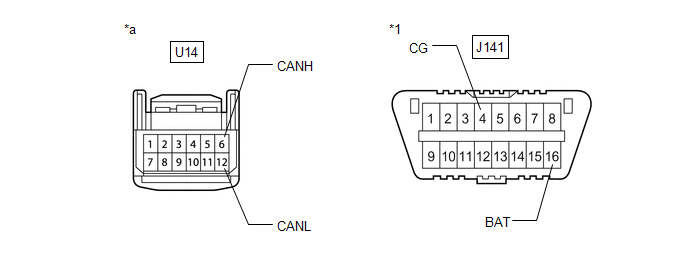
| *1 | DLC3 | - | - |
| *a | Front view of wire harness connector (to Forward Recognition Camera) | - | - |
(a) Disconnect the U14 forward recognition camera connector.
(b) Measure the resistance according to the value(s) in the table below.
Standard Resistance:
| Tester Connection | Condition | Specified Condition |
|---|---|---|
| U14-6 (CANH) - U14-12 (CANL) | Cable disconnected from negative (-) battery terminal | 108 to 132Ω |
(c) Measure the resistance according to the value(s) in the table below.
Standard Resistance:
| Tester Connection | Condition | Specified Condition |
|---|---|---|
| U14-6 (CANH) - J141-4 (CG) | Cable disconnected from negative (-) battery terminal | 200 Ω or higher |
| U14-12 (CANL) - J141-4 (CG) | Cable disconnected from negative (-) battery terminal | 200 Ω or higher |
| U14-6 (CANH) - J141-16 (BAT) | Cable disconnected from negative (-) battery terminal | 6 kΩ or higher |
| U14-12 (CANL) - J141-16 (BAT) | Cable disconnected from negative (-) battery terminal | 6 kΩ or higher |
(d) Connect the U14 forward recognition camera connector.
| OK | | REPLACE FORWARD RECOGNITION CAMERA |
| NG | | REPAIR OR REPLACE CAN BUS MAIN LINE OR CONNECTOR (FORWARD RECOGNITION CAMERA - NO. 1 CAN JUNCTION CONNECTOR) |
| 4. | CHECK CAN BUS LINES (MILLIMETER WAVE RADAR SENSOR ASSEMBLY - NO. 1 CAN JUNCTION CONNECTOR) |
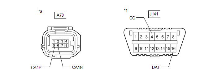
| *1 | DLC3 | - | - |
| *a | Front view of wire harness connector (to Millimeter Wave Radar Sensor Assembly) | - | - |
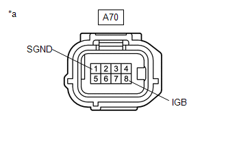
(a) Disconnect the A70 millimeter wave radar sensor assembly connector.
(b) Measure the resistance according to the value(s) in the table below.
Standard Resistance:
| Tester Connection | Condition | Specified Condition |
|---|---|---|
| A70-5 (CA1P) - A70-6 (CA1N) | Cable disconnected from negative (-) battery terminal | 108 to 132Ω |
(c) Measure the resistance according to the value(s) in the table below.
Standard Resistance:
| Tester Connection | Condition | Specified Condition |
|---|---|---|
| A70-5 (CA1P) - J141-4 (CG) | Cable disconnected from negative (-) battery terminal | 200 Ω or higher |
| A70-6 (CA1N) - J141-4 (CG) | Cable disconnected from negative (-) battery terminal | 200 Ω or higher |
| A70-5 (CA1P) - J141-16 (BAT) | Cable disconnected from negative (-) battery terminal | 6 kΩ or higher |
| A70-6 (CA1N) - J141-16 (BAT) | Cable disconnected from negative (-) battery terminal | 6 kΩ or higher |
(d) Connect the A70 millimeter wave radar sensor assembly connector.
| OK | | REPLACE MILLIMETER WAVE RADAR SENSOR ASSEMBLY |
| NG | | REPAIR OR REPLACE CAN BUS MAIN LINE OR CONNECTOR (MILLIMETER WAVE RADAR SENSOR ASSEMBLY - NO. 1 CAN JUNCTION CONNECTOR) |
| 5. | CHECK CONNECTOR (MILLIMETER WAVE RADAR SENSOR ASSEMBLY) |
(a) Check the locking part and terminals of the millimeter wave radar sensor assembly connector.
NOTICE:
- Make sure the connector is not loose or disconnected.
- Make sure that the connector and terminals are not deformed or damaged.
OK:
The connector and terminals are normal.
| NG | | REPAIR OR REPLACE HARNESS OR CONNECTOR (MILLIMETER WAVE RADAR SENSOR ASSEMBLY) |
|
| 6. | CHECK HARNESS AND CONNECTOR (POWER SOURCE CIRCUIT) |
(a) Disconnect the cable from the negative (-) battery terminal.
| (b) Disconnect the A70 millimeter wave radar sensor assembly connector. |
|
(c) Measure the resistance according to the value(s) in the table below.
Standard Resistance:
| Tester Connection | Condition | Specified Condition |
|---|---|---|
| A70-1 (SGND) - Body ground | Always | Below 1 Ω |
(d) Connect the cable to the negative (-) battery terminal.
(e) Measure the voltage according to the value(s) in the table below.
Standard Voltage:
| Tester Connection | Condition | Specified Condition |
|---|---|---|
| A70-8 (IGB) - Body ground | Engine switch on (IG) | 11 to 14 V |
(f) Connect the A70 millimeter wave radar sensor assembly connector.
| NG | | REPAIR OR REPLACE HARNESS OR CONNECTOR (POWER SOURCE CIRCUIT) |
|
| 7. | INSPECT MILLIMETER WAVE RADAR SENSOR ASSEMBLY (WAVEFORM) |
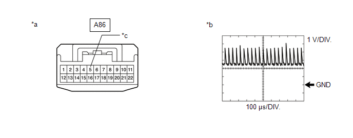
| *a | Front view of wire harness connector (to No. 1 CAN Junction Connector) | *b | Waveform |
| *c | to Millimeter Wave Radar Sensor Assembly | - | - |
(a) Turn the engine switch off.
(b) Disconnect the A86 No. 1 CAN junction connector.
(c) Turn the engine switch on (IG).
(d) Using an oscilloscope, measure the waveform at A86 No. 1 CAN junction connector.
Measurement Condition:
| Tester Connection | Condition | Tool Setting |
|---|---|---|
| A86-5 - Body ground | Engine switch on (IG) | 1 V/DIV., 100 μs/DIV. |
NOTICE:
The oscilloscope waveform is for reference only and does not include noise, fluctuations, etc.
OK:
A waveform similar to that in the illustration can be observed.
(e) Connect the A86 No. 1 CAN junction connector.
| OK | | REPLACE FORWARD RECOGNITION CAMERA |
| NG | | REPLACE MILLIMETER WAVE RADAR SENSOR ASSEMBLY |
 Lost Communication with ECM/PCM "A" Missing Message (U010087,U012587,U012687,U012987)
DESCRIPTION When a malfunction is detected between various ECUs and sensors, these DTCs are stored. DTC No. Detection Item DTC Detection Condition Trouble Area U010087 Lost Communicatio ...
 Lost Communication with Image Processing Module "A" Missing Message (U023A87)
DESCRIPTION The forward recognition camera communicates with the skid control ECU (brake actuator assembly) via CAN communication. If a communication error is detected between the skid control ECU (br ...
Other materials:
Lexus RX (RX 350L, RX450h) 2016-2025 Repair Manual > Seat Heater Control(for Rear Side): Installation
INSTALLATION CAUTION / NOTICE / HINT CAUTION: Wear protective gloves. Sharp areas on the seat frame may injure your hands. PROCEDURE 1. INSTALL SEAT HEATER CONTROL SUB-ASSEMBLY (w/o Rear No. 2 Seat) (a) for 60/40 Split Seat Type RH Side: (1) Engage the 2 clamps to install the seat heater control sub ...
Lexus RX (RX 350L, RX450h) 2016-2025 Repair Manual > Sfi System: Active Control Engine Mount System
DESCRIPTION LOCATION *1 No. 2 Vacuum Switching Valve Assembly (for Active Control Engine Mount) *2 Front Engine Mounting Insulator Assembly The active control engine mount system decreases engine vibration at a low engine speed using the No. 2 vacuum switching valve assembly (for active ...
Lexus RX (RX 350L, RX450h) 2016-{YEAR} Owners Manual
- For your information
- Pictorial index
- For safety and security
- Instrument cluster
- Operation of each component
- Driving
- Lexus Display Audio system
- Interior features
- Maintenance and care
- When trouble arises
- Vehicle specifications
- For owners
Lexus RX (RX 350L, RX450h) 2016-{YEAR} Repair Manual

0.0177