Lexus RX (RX 350L, RX450h) 2016-2026 Repair Manual: Active Control Engine Mount System
DESCRIPTION
LOCATION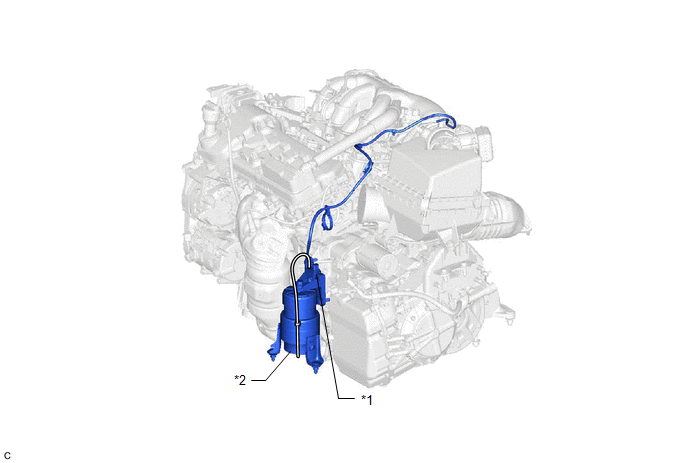
| *1 | No. 2 Vacuum Switching Valve Assembly (for Active Control Engine Mount) | *2 | Front Engine Mounting Insulator Assembly |
The active control engine mount system decreases engine vibration at a low engine speed using the No. 2 vacuum switching valve assembly (for active control engine mount). The No. 2 vacuum switching valve assembly (for active control engine mount) is controlled by a pulse signal transmitted to the No. 2 vacuum switching valve assembly (for active control engine mount) from the ECM. The frequency of this pulse signal is matched to the engine speed to decrease engine vibration.
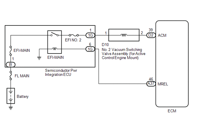
WIRING DIAGRAM
CAUTION / NOTICE / HINT
NOTICE:
Inspect the fuses for circuits related to this system before performing the following procedure.
PROCEDURE
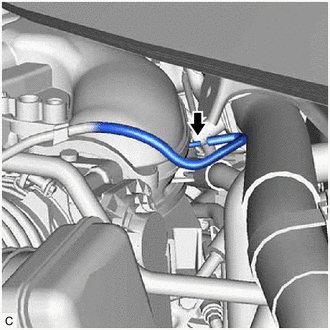
| 1. | CHECK VACUUM HOSES |
| (a) Check the air and vacuum hoses for looseness, disconnection and blockage. OK: No looseness, disconnection or blockage. |
|
| NG | .gif) | REPAIR OR REPLACE VACUUM HOSES |
|
.gif)
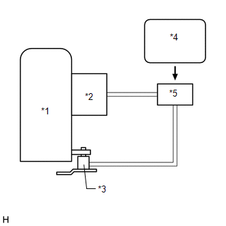
| 2. | CHECK VACUUM |
| (a) Disconnect the vacuum hose from the intake air surge tank assembly. |
|
(b) Start the engine.
(c) Check that the disconnected port located on the intake air surge tank assembly applies suction to your finger.
OK:
Vacuum exists.
| NG | | CHECK AND REPLACE VACUUM SOURCE AND HOSES |
|
| 3. | INSPECT NO. 2 VACUUM SWITCHING VALVE ASSEMBLY (FOR ACTIVE CONTROL ENGINE MOUNT) (OPERATION) |
(a) Inspect the No. 2 vacuum switching valve assembly (for active control engine mount) operation.
Click here .gif)
| NG | | REPLACE NO. 2 VACUUM SWITCHING VALVE ASSEMBLY (FOR ACTIVE CONTROL ENGINE MOUNT) |
|
| 4. | INSPECT NO. 2 VACUUM SWITCHING VALVE ASSEMBLY (FOR ACTIVE CONTROL ENGINE MOUNT) (RESISTANCE) |
(a) Inspect the No. 2 vacuum switching valve assembly (for active control engine mount) resistance.
Click here
| NG | | REPLACE NO. 2 VACUUM SWITCHING VALVE ASSEMBLY (FOR ACTIVE CONTROL ENGINE MOUNT) |
|
| 5. | INSPECT FRONT ENGINE MOUNTING INSULATOR |
(a) Inspect the front engine mounting insulator.
Click here
| NG | | REPLACE FRONT ENGINE MOUNTING INSULATOR |
|
| 6. | CHECK TERMINAL VOLTAGE (POWER SOURCE OF NO. 2 VACUUM SWITCHING VALVE ASSEMBLY (FOR ACTIVE CONTROL ENGINE MOUNT)) |
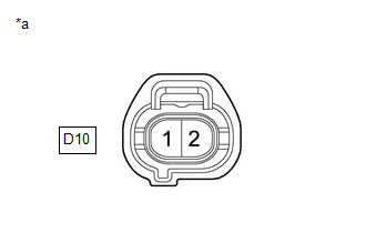
| *a | Front view of wire harness connector (to No. 2 Vacuum Switching Valve Assembly (for Active Control Engine Mount)) |
(a) Disconnect the No. 2 vacuum switching valve assembly (for active control engine mount) connector.
(b) Turn the engine switch on (IG).
(c) Measure the voltage according to the value(s) in the table below.
Standard Voltage:
| Tester Connection | Condition | Specified Condition |
|---|---|---|
| D10-1 - Body ground | Engine switch on (IG) | 11 to 14 V |
| NG | | GO TO STEP 8 |
|
| 7. | CHECK HARNESS AND CONNECTOR (NO. 2 VACUUM SWITCHING VALVE ASSEMBLY (FOR ACTIVE CONTROL ENGINE MOUNT) - ECM) |
(a) Disconnect the No. 2 vacuum switching valve assembly (for active control engine mount) connector.
(b) Disconnect the ECM connector.
(c) Measure the resistance according to the value(s) in the table below.
Standard Resistance:
| Tester Connection | Condition | Specified Condition |
|---|---|---|
| D10-2 - D2-39 (ACM) | Always | Below 1 Ω |
| D10-2 or D2-39 (ACM) - Body ground and other terminals | Always | 10 kΩ or higher |
| OK | | REPLACE ECM |
| NG | | REPAIR OR REPLACE HARNESS OR CONNECTOR |
| 8. | CHECK HARNESS AND CONNECTOR (SEMICONDUCTOR PWR INTEGRATION ECU - NO. 2 VACUUM SWITCHING VALVE ASSEMBLY (FOR ACTIVE CONTROL ENGINE MOUNT)) |
(a) Disconnect the semiconductor pwr integration ECU connector.
(b) Disconnect the No. 2 vacuum switching valve assembly (for active control engine mount) connector.
(c) Measure the resistance according to the value(s) in the table below.
Standard Resistance:
| Tester Connection | Condition | Specified Condition |
|---|---|---|
| 1G-1 - D10-1 | Always | Below 1 Ω |
| 1G-1 or D10-1 - Body ground and other terminals | Always | 10 kΩ or higher |
| OK | | GO TO ECM POWER SOURCE CIRCUIT |
| NG | | REPAIR OR REPLACE HARNESS OR CONNECTOR |
 Lost Communication with Instrument Panel Cluster (IPC) Control Module Missing Message (U015587)
DESCRIPTION The ECM and combination meter assembly send and receive signals via CAN communication. If a communication error occurs between the ECM and combination meter assembly, the ECM illuminates t ...
 ECM Power Source Circuit
DESCRIPTION When the engine switch is turned on (IG), the battery voltage is applied to the IGSW terminal of the ECM. The output signal from the MREL terminal of the ECM causes a current to flow to th ...
Other materials:
Lexus RX (RX 350L, RX450h) 2016-2026 Owners Manual > For safe use: Before driving
Floor mat
Use only floor mats designed specifically for vehicles of the same model and
model year as your vehicle. Fix them securely in place onto the carpet.
1. Insert the retaining hooks (clips) into
the floor mat eyelets.
2. Turn the upper knob of each retaining
hook (clip) to secure the ...
Lexus RX (RX 350L, RX450h) 2016-2026 Repair Manual > Wiper / Washer: Headlight Cleaner Actuator Cover
RemovalREMOVAL PROCEDURE 1. REMOVE HEADLIGHT WASHER COVER LH (a) Disengage the claw as indicated by the arrows, in the order shown in the illustration to remove the headlight washer cover LH. Remove in this Direction (1) Remove in this Direction (2) 2. REMOVE HEADLIGHT WASHER COVER ...
Lexus RX (RX 350L, RX450h) 2016-{YEAR} Owners Manual
- For your information
- Pictorial index
- For safety and security
- Instrument cluster
- Operation of each component
- Driving
- Lexus Display Audio system
- Interior features
- Maintenance and care
- When trouble arises
- Vehicle specifications
- For owners
Lexus RX (RX 350L, RX450h) 2016-{YEAR} Repair Manual

0.0142