Lexus RX (RX 350L, RX450h) 2016-2026 Repair Manual: ECM Power Source Circuit
DESCRIPTION
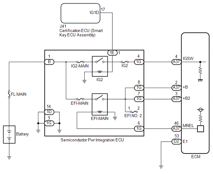
When the engine switch is turned on (IG), the battery voltage is applied to the IGSW terminal of the ECM.
The output signal from the MREL terminal of the ECM causes a current to flow to the coil of the semiconductor pwr integration ECU (EFI-MAIN relay), closing the contacts and supplying power to terminals +B and +B2 of the ECM.
WIRING DIAGRAM
CAUTION / NOTICE / HINT
NOTICE:
Inspect the fuses for circuits related to this system before performing the following inspection procedure.
PROCEDURE
| 1. | CHECK SEMICONDUCTOR POWER INTEGRATION ECU (POWER SOURCE) |
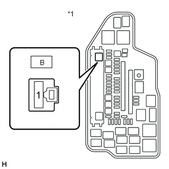
| *1 | Engine Room Relay Block and Junction Block Assembly |
(a) Disconnect the semiconductor pwr integration ECU connector.
(b) Measure the voltage according to the value(s) in the table below.
Standard Voltage:
| Tester Connection | Condition | Specified Condition |
|---|---|---|
| B-1 - Body ground | Always | 11 to 14 V |
| NG | .gif) | REPAIR OR REPLACE HARNESS OR CONNECTOR (BATTERY - SEMICONDUCTOR PWR INTEGRATION ECU) |
|
.gif)
| 2. | CHECK HARNESS AND CONNECTOR (SEMICONDUCTOR PWR INTEGRATION ECU - BODY GROUND) |
(a) Disconnect the semiconductor pwr integration ECU connector.
(b) Measure the resistance according to the value(s) in the table below.
Standard Resistance:
| Tester Connection | Condition | Specified Condition |
|---|---|---|
| 1D-14 - Body ground | Always | Below 1 Ω |
| 1G-5 - Body ground | Always | Below 1 Ω |
| NG | | REPAIR OR REPLACE HARNESS OR CONNECTOR |
|
| 3. | INSPECT SEMICONDUCTOR POWER INTEGRATION ECU (EFI-MAIN RELAY, IG2 RELAY) |
(a) Inspect the semiconductor pwr integration ECU (EFI-MAIN relay, IG2 relay).
Click here .gif)
| NG | | REPLACE SEMICONDUCTOR POWER INTEGRATION ECU |
|
| 4. | CHECK HARNESS AND CONNECTOR (SEMICONDUCTOR PWR INTEGRATION ECU - ECM) |
(a) Disconnect the semiconductor pwr integration ECU connector.
(b) Disconnect the ECM connector.
(c) Measure the resistance according to the value(s) in the table below.
Standard Resistance:
| Tester Connection | Condition | Specified Condition |
|---|---|---|
| 1G-4 - A37-4 (IGSW) | Always | Below 1 Ω |
| 1G-6 - A37-46 (MREL) | Always | Below 1 Ω |
| 1G-8 - A37-2 (+B) | Always | Below 1 Ω |
| 1G-7 - A37-3 (+B2) | Always | Below 1 Ω |
| 1G-4 or A37-4 (IGSW) - Body ground and other terminals | Always | 10 kΩ or higher |
| 1G-6 or A37-46 (MREL) - Body ground and other terminals | Always | 10 kΩ or higher |
| 1G-8 or A37-2 (+B) - Body ground and other terminals | Always | 10 kΩ or higher |
| 1G-7 or A37-3 (+B2) - Body ground and other terminals | Always | 10 kΩ or higher |
HINT:
If a short is detected in any of the above circuits, there may be a malfunction in the circuit of a connected ECU.
| NG | | REPAIR OR REPLACE HARNESS OR CONNECTOR |
|
| 5. | CHECK HARNESS AND CONNECTOR (ECM - BODY GROUND) |
(a) Disconnect the ECM connector.
(b) Measure the resistance according to the value(s) in the table below.
Standard Resistance:
| Tester Connection | Condition | Specified Condition |
|---|---|---|
| D2-53 (E1) - Body ground | Always | Below 1 Ω |
| NG | | REPAIR OR REPLACE HARNESS OR CONNECTOR |
|
| 6. | CHECK HARNESS AND CONNECTOR (CERTIFICATION ECU (SMART KEY ECU ASSEMBLY) - SEMICONDUCTOR PWR INTEGRATION ECU) |
(a) Disconnect the certification ECU (smart key ECU assembly) connector.
(b) Disconnect the semiconductor pwr integration ECU connector.
(c) Measure the resistance according to the value(s) in the table below.
Standard Resistance:
| Tester Connection | Condition | Specified Condition |
|---|---|---|
| J41-17 (IG1D) - 1E-1 | Always | Below 1 Ω |
| J41-17 (IG1D) or 1E-1 - Body ground and other terminals | Always | 10 kΩ or higher |
HINT:
If a short is detected in any of the above circuits, there may be a malfunction in the circuit of a connected ECU.
| OK | | CHECK SMART ACCESS SYSTEM WITH PUSH-BUTTON START |
| NG | | REPAIR OR REPLACE HARNESS OR CONNECTOR |
 Active Control Engine Mount System
DESCRIPTION LOCATION *1 No. 2 Vacuum Switching Valve Assembly (for Active Control Engine Mount) *2 Front Engine Mounting Insulator Assembly The active control engine mount system decrease ...
 EVAP System
RELATED DTCS DTC No. SAE Monitoring Item Link P00FE00 P00FE EVAP vent line blocked P043E00 P043E Reference orifice clogged (built into canister pump module) P043 ...
Other materials:
Lexus RX (RX 350L, RX450h) 2016-2026 Repair Manual > Ignition Coil And Spark Plug: Removal
REMOVAL CAUTION / NOTICE / HINT The necessary procedures (adjustment, calibration, initialization or registration) that must be performed after parts are removed and installed, or replaced during ignition coil assembly or spark plug removal/installation are shown below. Necessary Procedure After Par ...
Lexus RX (RX 350L, RX450h) 2016-2026 Repair Manual > Steering Gear: Disassembly
DISASSEMBLY PROCEDURE 1. REMOVE STEERING RACK BOOT CLIP (for LH Side) (a) Using pliers, remove the steering rack boot clip. 2. REMOVE STEERING RACK BOOT CLIP (for RH Side) HINT: Perform the same procedure as for the LH side. 3. REMOVE NO. 2 STEERING RACK BOOT CLAMP (for LH Side) (a) Using a screw ...
Lexus RX (RX 350L, RX450h) 2016-{YEAR} Owners Manual
- For your information
- Pictorial index
- For safety and security
- Instrument cluster
- Operation of each component
- Driving
- Lexus Display Audio system
- Interior features
- Maintenance and care
- When trouble arises
- Vehicle specifications
- For owners
Lexus RX (RX 350L, RX450h) 2016-{YEAR} Repair Manual

0.0093