Lexus RX (RX 350L, RX450h) 2016-2026 Repair Manual: Right Rear Wheel Speed Sensor Circuit Short to Battery (C051212)
DESCRIPTION
Refer to DTC C05121F.
Click here .gif)
| DTC No. | Detection Item | DTC Detection Condition | Trouble Area |
|---|---|---|---|
| C051212 | Right Rear Wheel Speed Sensor Circuit Short to Battery | The speed sensor short signal is ON continuously for 0.5 seconds or more. |
|
- *1: for AWD
- *2: for 2WD
- *3: w/ AVS
WIRING DIAGRAM
Click here
CAUTION / NOTICE / HINT
NOTICE:
-
After replacing the skid control ECU (brake actuator assembly), perform "Calibration".
Click here
-
After replacing or removing and installing a speed sensor, perform Dealer Mode (Signal Check) inspection to confirm that the speed sensors are operating correctly.
Click here
PROCEDURE
| 1. | CHECK VEHICLE SPECIFICATION |
(a) Check the vehicle specification.
| Result | Proceed to |
|---|---|
| w/o AVS (for AWD) | A |
| w/o AVS (for 2WD) | B |
| w/ AVS (for AWD) | C |
| w/ AVS (for 2WD) | D |
| B | .gif) | GO TO STEP 5 |
| C | | GO TO STEP 9 |
| D | | GO TO STEP 13 |
|
.gif)
| 2. | CHECK HARNESS AND CONNECTOR (SENSOR GROUND CIRCUIT) |
| (a) Make sure that there is no looseness at the locking part and the connecting part of the connectors. OK: The connector is securely connected. |
|
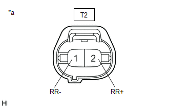
(b) Disconnect the T2 rear speed sensor RH connector.
(c) Check both the connector case and the terminals for deformation and corrosion.
OK:
No deformation or corrosion.
(d) Turn the engine switch on (IG).
(e) Measure the voltage according to the value(s) in the table below.
Standard Voltage:
| Tester Connection | Condition | Specified Condition |
|---|---|---|
| T2-2 (RR+) - T2-1 (RR-) | Engine switch on (IG) | 11 to 14 V |
| OK | | REPLACE REAR SPEED SENSOR RH |
|
| 3. | CHECK HARNESS AND CONNECTOR (SENSOR GROUND CIRCUIT) |
| (a) Turn the engine switch off. |
|
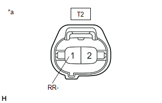
(b) Make sure that there is no looseness at the locking part and the connecting part of the connectors.
OK:
The connector is securely connected.
(c) Disconnect the A41 skid control ECU (brake actuator assembly) connector.
(d) Check both the connector case and the terminals for deformation and corrosion.
OK:
No deformation or corrosion.
(e) Measure the voltage according to the value(s) in the table below.
Standard Voltage:
| Tester Connection | Condition | Specified Condition |
|---|---|---|
| T2-1 (RR-) - Body ground | Always | Below 1.5 V |
| NG | | REPAIR OR REPLACE HARNESS OR CONNECTOR |
|
| 4. | CHECK HARNESS AND CONNECTOR (REAR SPEED SENSOR RH - BRAKE ACTUATOR ASSEMBLY) |
(a) Measure the resistance according to the value(s) in the table below.
Standard Resistance:
| Tester Connection | Condition | Specified Condition |
|---|---|---|
| T2-2 (RR+) or A41-20 (RR+) - T2-1 (RR-) or A41-19 (RR-) | Always | 10 kΩ or higher |
| OK | | REPLACE BRAKE ACTUATOR ASSEMBLY |
| NG | | REPAIR OR REPLACE HARNESS OR CONNECTOR |
| 5. | CHECK HARNESS AND CONNECTOR (SENSOR GROUND CIRCUIT) |
| (a) Make sure that there is no looseness at the locking part and the connecting part of the connectors. OK: The connector is securely connected. |
|
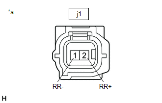
(b) Disconnect the j1 rear speed sensor RH (rear axle hub and bearing assembly RH) connector.
(c) Check both the connector case and the terminals for deformation and corrosion.
OK:
No deformation or corrosion.
(d) Turn the engine switch on (IG).
(e) Measure the voltage according to the value(s) in the table below.
Standard Voltage:
| Tester Connection | Condition | Specified Condition |
|---|---|---|
| j1-2 (RR+) - j1-1 (RR-) | Engine switch on (IG) | 11 to 14 V |
HINT:
The rear speed sensor RH is incorporated into the rear axle hub and bearing assembly RH.
If the rear speed sensor RH needs to be replaced, replace the rear axle hub and bearing assembly RH.
| OK | | REPLACE REAR AXLE HUB AND BEARING ASSEMBLY RH |
|
| 6. | CHECK HARNESS AND CONNECTOR (SENSOR GROUND CIRCUIT) |
| (a) Turn the engine switch off. |
|
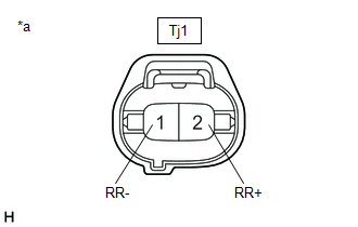
(b) Make sure that there is no looseness at the locking part and the connecting part of the connectors.
OK:
The connector is securely connected.
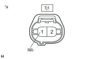
(c) Disconnect the Tj1 rear skid control sensor wire RH No. 1 connector.
(d) Check both the connector case and the terminals for deformation and corrosion.
OK:
No deformation or corrosion.
(e) Turn the engine switch on (IG).
(f) Measure the voltage according to the value(s) in the table below.
Standard Voltage:
| Tester Connection | Condition | Specified Condition |
|---|---|---|
| Tj1-2 (RR+) - Tj1-1 (RR-) | Engine switch on (IG) | 11 to 14 V |
| OK | | REPLACE REAR SKID CONTROL SENSOR WIRE RH NO. 1 |
|
| 7. | CHECK HARNESS AND CONNECTOR (SENSOR GROUND CIRCUIT) |
| (a) Turn the engine switch off. |
|
(b) Make sure that there is no looseness at the locking part and the connecting part of the connectors.
OK:
The connector is securely connected.
(c) Disconnect the A41 skid control ECU (brake actuator assembly) connector.
(d) Check both the connector case and the terminals for deformation and corrosion.
OK:
No deformation or corrosion.
(e) Measure the voltage according to the value(s) in the table below.
Standard Voltage:
| Tester Connection | Condition | Specified Condition |
|---|---|---|
| Tj1-1 (RR-) - Body ground | Always | Below 1.5 V |
| NG | | REPAIR OR REPLACE HARNESS OR CONNECTOR |
|
| 8. | CHECK HARNESS AND CONNECTOR (REAR SKID CONTROL SENSOR WIRE RH NO. 1 - BRAKE ACTUATOR ASSEMBLY) |
(a) Measure the resistance according to the value(s) in the table below.
Standard Resistance:
| Tester Connection | Condition | Specified Condition |
|---|---|---|
| Tj1-2 (RR+) or A41-20 (RR+) - Tj1-1 (RR-) or A41-19 (RR-) | Always | 10 kΩ or higher |
| OK | | REPLACE BRAKE ACTUATOR ASSEMBLY |
| NG | | REPAIR OR REPLACE HARNESS OR CONNECTOR |
| 9. | CHECK HARNESS AND CONNECTOR (SENSOR GROUND CIRCUIT) |
| (a) Make sure that there is no looseness at the locking part and the connecting part of the connectors. OK: The connector is securely connected. |
|
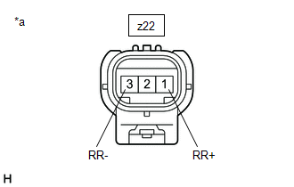
(b) Disconnect the z22 rear speed sensor RH connector.
(c) Check both the connector case and the terminals for deformation and corrosion.
OK:
No deformation or corrosion.
(d) Turn the engine switch on (IG).
(e) Measure the voltage according to the value(s) in the table below.
Standard Voltage:
| Tester Connection | Condition | Specified Condition |
|---|---|---|
| z22-1 (RR+) - z22-3 (RR-) | Engine switch on (IG) | 11 to 14 V |
| OK | | REPLACE REAR SPEED SENSOR RH |
|
| 10. | CHECK HARNESS AND CONNECTOR (SENSOR GROUND CIRCUIT) |
| (a) Turn the engine switch off. |
|
(b) Make sure that there is no looseness at the locking part and the connecting part of the connectors.
OK:
The connector is securely connected.
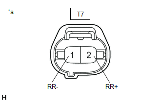
(c) Disconnect the T7 rear skid control sensor wire RH NO. 2 connector.
(d) Check both the connector case and the terminals for deformation and corrosion.
OK:
No deformation or corrosion.
(e) Turn the engine switch on (IG).
(f) Measure the voltage according to the value(s) in the table below.
Standard Voltage:
| Tester Connection | Condition | Specified Condition |
|---|---|---|
| T7-2 (RR+) - T7-1 (RR-) | Engine switch on (IG) | 11 to 14 V |
| OK | | REPLACE REAR SKID CONTROL SENSOR WIRE RH NO. 2 |
|
| 11. | CHECK HARNESS AND CONNECTOR (SENSOR GROUND CIRCUIT) |
| (a) Turn the engine switch off. |
|
(b) Make sure that there is no looseness at the locking part and the connecting part of the connectors.
OK:
The connector is securely connected.
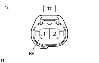
(c) Disconnect the A41 skid control ECU (brake actuator assembly) connector.
(d) Check both the connector case and the terminals for deformation and corrosion.
OK:
No deformation or corrosion.
(e) Measure the voltage according to the value(s) in the table below.
Standard Voltage:
| Tester Connection | Condition | Specified Condition |
|---|---|---|
| T7-1 (RR-) - Body ground | Always | Below 1.5 V |
| NG | | REPAIR OR REPLACE HARNESS OR CONNECTOR |
|
| 12. | CHECK HARNESS AND CONNECTOR (REAR SKID CONTROL SENSOR WIRE RH NO. 2 - BRAKE ACTUATOR ASSEMBLY) |
(a) Measure the resistance according to the value(s) in the table below.
Standard Resistance:
| Tester Connection | Condition | Specified Condition |
|---|---|---|
| T7-2 (RR+) or A41-20 (RR+) - T7-1 (RR-) or A41-19 (RR-) | Always | 10 kΩ or higher |
| OK | | REPLACE BRAKE ACTUATOR ASSEMBLY |
| NG | | REPAIR OR REPLACE HARNESS OR CONNECTOR |
| 13. | CHECK HARNESS AND CONNECTOR (SENSOR GROUND CIRCUIT) |
| (a) Make sure that there is no looseness at the locking part and the connecting part of the connectors. OK: The connector is securely connected. |
|
(b) Disconnect the j1 rear speed sensor RH (rear axle hub and bearing assembly RH) connector.
(c) Check both the connector case and the terminals for deformation and corrosion.
OK:
No deformation or corrosion.
(d) Turn the engine switch on (IG).
(e) Measure the voltage according to the value(s) in the table below.
Standard Voltage:
| Tester Connection | Condition | Specified Condition |
|---|---|---|
| j1-2 (RR+) - j1-1 (RR-) | Engine switch on (IG) | 11 to 14 V |
HINT:
The rear speed sensor RH is incorporated into the rear axle hub and bearing assembly RH.
If the rear speed sensor RH needs to be replaced, replace the rear axle hub and bearing assembly RH.
| OK | | REPLACE REAR AXLE HUB AND BEARING ASSEMBLY RH |
|
| 14. | CHECK HARNESS AND CONNECTOR (SENSOR GROUND CIRCUIT) |
| (a) Turn the engine switch off. |
|
(b) Make sure that there is no looseness at the locking part and the connecting part of the connectors.
OK:
The connector is securely connected.
(c) Disconnect the j5 rear skid control sensor wire RH No. 1 connector.
(d) Check both the connector case and the terminals for deformation and corrosion.
OK:
No deformation or corrosion.
(e) Turn the engine switch on (IG).
(f) Measure the voltage according to the value(s) in the table below.
Standard Voltage:
| Tester Connection | Condition | Specified Condition |
|---|---|---|
| j5-1 (RR+) - j5-3 (RR-) | Engine switch on (IG) | 11 to 14 V |
| OK | | REPLACE REAR SKID CONTROL SENSOR WIRE RH NO. 1 |
|
| 15. | CHECK HARNESS AND CONNECTOR (SENSOR GROUND CIRCUIT) |
| (a) Turn the engine switch off. |
|
(b) Make sure that there is no looseness at the locking part and the connecting part of the connectors.
OK:
The connector is securely connected.
(c) Disconnect the T7 rear skid control sensor wire RH No. 2 connector.
(d) Check both the connector case and the terminals for deformation and corrosion.
OK:
No deformation or corrosion.
(e) Turn the engine switch on (IG).
(f) Measure the voltage according to the value(s) in the table below.
Standard Voltage:
| Tester Connection | Condition | Specified Condition |
|---|---|---|
| T7-2 (RR+) - T7-1 (RR-) | Engine switch on (IG) | 11 to 14 V |
| OK | | REPLACE REAR SKID CONTROL SENSOR WIRE RH NO. 2 |
|
| 16. | CHECK HARNESS AND CONNECTOR (SENSOR GROUND CIRCUIT) |
| (a) Turn the engine switch off. |
|
(b) Make sure that there is no looseness at the locking part and the connecting part of the connectors.
OK:
The connector is securely connected.
(c) Disconnect the A41 skid control ECU (brake actuator assembly) connector.
(d) Check both the connector case and the terminals for deformation and corrosion.
OK:
No deformation or corrosion.
(e) Measure the voltage according to the value(s) in the table below.
Standard Voltage:
| Tester Connection | Condition | Specified Condition |
|---|---|---|
| T7-1 (RR-) - Body ground | Always | Below 1.5 V |
| NG | | REPAIR OR REPLACE HARNESS OR CONNECTOR |
|
| 17. | CHECK HARNESS AND CONNECTOR (REAR SKID CONTROL SENSOR WIRE RH NO. 2 - BRAKE ACTUATOR ASSEMBLY) |
(a) Measure the resistance according to the value(s) in the table below.
Standard Resistance:
| Tester Connection | Condition | Specified Condition |
|---|---|---|
| T7-2 (RR+) or A41-20 (RR+) - T7-1 (RR-) or A41-19 (RR-) | Always | 10 kΩ or higher |
| OK | | REPLACE BRAKE ACTUATOR ASSEMBLY |
| NG | | REPAIR OR REPLACE HARNESS OR CONNECTOR |
 Left Rear Wheel Speed Sensor Signal Has Too Many Pulses (C050C3A,C05123A)
DESCRIPTION Refer to DTC C050C1F. Click here DTC No. Detection Item DTC Detection Condition Trouble Area C050C3A Left Rear Wheel Speed Sensor Signal Has Too Many Pulses When not in ...
 Right Rear Wheel Speed Sensor Circuit Short to Ground or Open (C051214)
DESCRIPTION Refer to DTC C05121F. Click here DTC No. Detection Item DTC Detection Condition Trouble Area C051214 Right Rear Wheel Speed Sensor Circuit Short to Ground or Open An ope ...
Other materials:
Lexus RX (RX 350L, RX450h) 2016-2026 Repair Manual > Rear No. 1 Seat Inner Belt Assembly(for Captain Seat Type): Components
COMPONENTS ILLUSTRATION *1 CUP HOLDER ASSEMBLY *2 NO. 1 RECLINING ADJUSTER RELEASE HANDLE LH *3 REAR NO. 1 SEAT RECLINING ADJUSTER INSIDE COVER *4 REAR SEAT COVER CAP LH *5 REAR SEAT INNER BELT ASSEMBLY LH *6 REAR SEAT INNER RECLINING COVER LH *7 REAR SEAT LOCK CO ...
Lexus RX (RX 350L, RX450h) 2016-2026 Repair Manual > Lane Control System: Steering Pad Switch Circuit
DESCRIPTION The forward recognition camera receives LTA main switch signals from the steering pad switch assembly. WIRING DIAGRAM CAUTION / NOTICE / HINT NOTICE: The vehicle is equipped with a Supplemental Restraint System (SRS) which includes components such as airbags. Before servicing (including ...
Lexus RX (RX 350L, RX450h) 2016-{YEAR} Owners Manual
- For your information
- Pictorial index
- For safety and security
- Instrument cluster
- Operation of each component
- Driving
- Lexus Display Audio system
- Interior features
- Maintenance and care
- When trouble arises
- Vehicle specifications
- For owners
Lexus RX (RX 350L, RX450h) 2016-{YEAR} Repair Manual

0.0104