Lexus RX (RX 350L, RX450h) 2016-2025 Repair Manual: Right Rear Wheel Speed Sensor Circuit Short to Ground or Open (C051214)
DESCRIPTION
Refer to DTC C05121F.
Click here .gif)
| DTC No. | Detection Item | DTC Detection Condition | Trouble Area |
|---|---|---|---|
| C051214 | Right Rear Wheel Speed Sensor Circuit Short to Ground or Open | An open in the speed sensor signal circuit continues for 0.5 seconds or more. |
|
- *1: for AWD
- *2: for 2WD
- *3: w/ AVS
WIRING DIAGRAM
Click here
CAUTION / NOTICE / HINT
NOTICE:
-
After replacing the skid control ECU (brake actuator assembly), perform "Calibration".
Click here
-
After replacing or removing and installing a speed sensor, perform Dealer Mode (Signal Check) inspection to confirm that the speed sensors are operating correctly.
Click here
PROCEDURE
| 1. | READ VALUE USING TECHSTREAM (MOMENTARY INTERRUPTION) |
(a) Connect the Techstream to the DLC3.
(b) Turn the engine switch on (IG).
(c) Enter the following menus: Chassis / Brake/EPB / Data List.
Chassis > Brake/EPB > Data List| Tester Display | Measurement Item | Range | Normal Condition | Diagnostic Note |
|---|---|---|---|---|
| RR Speed Open | Rear speed sensor RH open detection | Under intermittent / Normal | Under intermittent: Momentary interruption detected Normal: Momentary interruption not detected | - |
| Tester Display |
|---|
| RR Speed Open |
(d) Select the line graph display.
(e) Check for any momentary interruption in the wire harness and connector.
Click here
OK:
Normal (There are no momentary interruptions.)
NOTICE:
Perform the above inspection before removing the sensor and connector.
| NG | .gif) | GO TO STEP 5 |
|
.gif)
| 2. | READ VALUE USING TECHSTREAM (RR WHEEL SPEED) |
(a) Enter the following menus: Chassis / Brake/EPB / Data List.
Chassis > Brake/EPB > Data List| Tester Display | Measurement Item | Range | Normal Condition | Diagnostic Note |
|---|---|---|---|---|
| RR Wheel Speed | Rear wheel speed sensor RH reading | Min.: 0.0 km/h (0.0 mph) Max.: 6553.5 km/h (4072 mph) | Vehicle stopped: 0.0 km/h (0.0 mph) | When driving at constant speed: No large fluctuations |
| Tester Display |
|---|
| RR Wheel Speed |
(b) Start the engine.
(c) Perform a road test.
(d) Check the speed value output from the speed sensor displayed on the Techstream.
HINT:
Factors that affect the indicated vehicle speed include tire size, tire pressure, and tire wear. The speed indicated on the speedometer has an allowable margin of error. This can be tested using a speedometer tester (calibrated chassis dynamometer). For details about testing and the margin of error, see the reference chart.
Click here
OK:
The speed value output from the speed sensor displayed on the Techstream is similar to the speed indicated on the speedometer.
| NG | | GO TO STEP 5 |
|
| 3. | CLEAR DTC |
(a) Operate the Techstream to clear the codes. Enter the following menus: Chassis / Brake/EPB / Trouble Codes.
Chassis > Brake/EPB > Clear DTCs(b) Press the DTC clear button.
(c) Turn the engine switch off.
|
| 4. | RECONFIRM DTC |
(a) Start the engine.
(b) Perform a road test.
(c) Read the DTCs following the prompts on the Techstream. Enter the following menus: Chassis / Brake/EPB / Trouble Codes.
Chassis > Brake/EPB > Trouble Codes(d) Check if the same DTC is output.
| Result | Proceed to |
|---|---|
| DTC C051214 is not output. | A |
| DTC C051214 is output. | B |
| A | | USE SIMULATION METHOD TO CHECK |
| B | | REPLACE BRAKE ACTUATOR ASSEMBLY |
| 5. | CHECK VEHICLE SPECIFICATION |
(a) Check the vehicle specification.
| Result | Proceed to |
|---|---|
| w/o AVS (for AWD) | A |
| w/o AVS (for 2WD) | B |
| w/ AVS (for AWD) | C |
| w/ AVS (for 2WD) | D |
| B | | GO TO STEP 8 |
| C | | GO TO STEP 11 |
| D | | GO TO STEP 14 |
|
| 6. | INSPECT HARNESS AND CONNECTOR (REAR SPEED SENSOR RH - BRAKE ACTUATOR ASSEMBLY) |
(a) Turn the engine switch off.
(b) Make sure that there is no looseness at the locking part and the connecting part of the connectors.
OK:
The connector is securely connected.
(c) Disconnect the A41 skid control ECU (brake actuator assembly) connector.
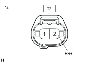
(d) Disconnect the T2 rear speed sensor RH connector.
(e) Check both the connector case and the terminals for deformation and corrosion.
OK:
No deformation or corrosion.
(f) Measure the resistance according to the value(s) in the table below.
Standard Resistance:
| Tester Connection | Condition | Specified Condition |
|---|---|---|
| T2-2 (RR+) - A41-20 (RR+) | Always | Below 1 Ω |
| T2-2 (RR+) or A41-20 (RR+) - Body ground | Always | 10 kΩ or higher |
| T2-1 (RR-) - A41-19 (RR-) | Always | Below 1 Ω |
| T2-1 (RR-) or A41-19 (RR-) - Body ground | Always | 10 kΩ or higher |
| NG | | REPAIR OR REPLACE HARNESS OR CONNECTOR |
|
| 7. | INSPECT BRAKE ACTUATOR ASSEMBLY (SENSOR POWER SOURCE CIRCUIT) |
| (a) Reconnect the A41 skid control ECU (brake actuator assembly) connector. |
|
(b) Make sure that there is no looseness at the locking part and the connecting part of the connectors.
OK:
The connector is securely connected.
(c) Turn the engine switch on (IG).
(d) Measure the voltage according to the value(s) in the table below.
Standard Voltage:
| Tester Connection | Condition | Specified Condition |
|---|---|---|
| T2-2 (RR+) - Body ground | Engine switch on (IG) | 11 to 14 V |
| OK | | REPLACE REAR SPEED SENSOR RH |
| NG | | REPLACE BRAKE ACTUATOR ASSEMBLY |
| 8. | INSPECT REAR SKID CONTROL SENSOR WIRE RH NO. 1 |
| (a) Turn the engine switch off. |
|
(b) Make sure that there is no looseness at the locking part and the connecting part of the connectors.
OK:
The connector is securely connected.
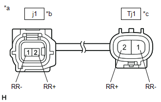
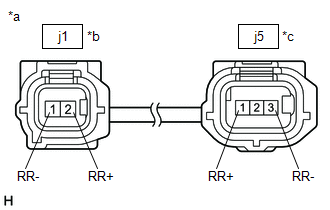
(c) Disconnect the j1 and Tj1 rear skid control sensor wire RH No. 1 connector.
(d) Check both the connector case and the terminals for deformation and corrosion.
OK:
No deformation or corrosion.
(e) Measure the resistance according to the value(s) in the table below.
Standard Resistance:
| Tester Connection | Condition | Specified Condition |
|---|---|---|
| j1-2 (RR+) - Tj1-2 (RR+) | Always | Below 1 Ω |
| j1-2 (RR+) or Tj1-2 (RR+) - Body ground and other terminals | Always | 10 kΩ or higher |
| j1-1 (RR-) - Tj1-1 (RR-) | Always | Below 1 Ω |
| j1-1 (RR-) or Tj1-1 (RR-) - Body ground and other terminals | Always | 10 kΩ or higher |
| NG | | REPLACE REAR SKID CONTROL SENSOR WIRE RH NO. 1 |
|
| 9. | CHECK HARNESS AND CONNECTOR (REAR SKID CONTROL SENSOR WIRE RH NO. 1 - BRAKE ACTUATOR ASSEMBLY) |
(a) Make sure that there is no looseness at the locking part and the connecting part of the connectors.
OK:
The connector is securely connected.
(b) Disconnect the A41 skid control ECU (brake actuator assembly) connector.
(c) Check both the connector case and the terminals for deformation and corrosion.
OK:
No deformation or corrosion.
(d) Measure the resistance according to the value(s) in the table below.
Standard Resistance:
| Tester Connection | Condition | Specified Condition |
|---|---|---|
| Tj1-2 (RR+) - A41-20 (RR+) | Always | Below 1 Ω |
| Tj1-2 (RR+) or A41-20 (RR+) - Body ground | Always | 10 kΩ or higher |
| Tj1-1 (RR-) - A41-19 (RR-) | Always | Below 1 Ω |
| Tj1-1 (RR-) or A41-19 (RR-) - Body ground | Always | 10 kΩ or higher |
| NG | | REPAIR OR REPLACE HARNESS OR CONNECTOR |
|
| 10. | INSPECT BRAKE ACTUATOR ASSEMBLY (SENSOR POWER SOURCE CIRCUIT) |
| (a) Reconnect the A41 skid control ECU (brake actuator assembly) connector. |
|

(b) Reconnect the Tj1 rear skid control sensor wire RH No. 1 connector.
(c) Make sure that there is no looseness at the locking part and the connecting part of the connectors.
OK:
The connector is securely connected.
(d) Turn the engine switch on (IG).
(e) Measure the voltage according to the value(s) in the table below.
Standard Voltage:
| Tester Connection | Condition | Specified Condition |
|---|---|---|
| j1-2 (RR+) - Body ground | Engine switch on (IG) | 11 to 14 V |
HINT:
The rear speed sensor RH is incorporated into the rear axle hub and bearing assembly RH.
If the rear speed sensor RH needs to be replaced, replace the rear axle hub and bearing assembly RH.
| OK | | REPLACE REAR AXLE HUB AND BEARING ASSEMBLY RH |
| NG | | REPLACE BRAKE ACTUATOR ASSEMBLY |
| 11. | INSPECT REAR SKID CONTROL SENSOR WIRE RH NO. 2 |
| (a) Turn the engine switch off. |
|
(b) Make sure that there is no looseness at the locking part and the connecting part of the connectors.
OK:
The connector is securely connected.
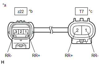
(c) Disconnect the z22 and T7 rear skid control sensor wire RH No. 2 connector.
(d) Check both the connector case and the terminals for deformation and corrosion.
OK:
No deformation or corrosion.
(e) Measure the resistance according to the value(s) in the table below.
Standard Resistance:
| Tester Connection | Condition | Specified Condition |
|---|---|---|
| z22-1 (RR+) - T7-2 (RR+) | Always | Below 1 Ω |
| z22-1 (RR+) or T7-2 (RR+) - Body ground and other terminals | Always | 10 kΩ or higher |
| z22-3 (RR-) - T7-1 (RR-) | Always | Below 1 Ω |
| z22-3 (RR-) or T7-1 (RR-) - Body ground and other terminals | Always | 10 kΩ or higher |
| NG | | REPLACE REAR SKID CONTROL SENSOR WIRE RH NO. 2 |
|
| 12. | INSPECT HARNESS AND CONNECTOR (REAR SKID CONTROL SENSOR WIRE RH NO. 2 - BRAKE ACTUATOR ASSEMBLY) |
(a) Make sure that there is no looseness at the locking part and the connecting part of the connectors.
OK:
The connector is securely connected.
(b) Disconnect the A41 skid control ECU (brake actuator assembly) connector.
(c) Check both the connector case and the terminals for deformation and corrosion.
OK:
No deformation or corrosion.
(d) Measure the resistance according to the value(s) in the table below.
Standard Resistance:
| Tester Connection | Condition | Specified Condition |
|---|---|---|
| T7-2 (RR+) - A41-20 (RR+) | Always | Below 1 Ω |
| T7-2 (RR+) or A41-20 (RR+) - Body ground | Always | 10 kΩ or higher |
| T7-1 (RR-) - A41-19 (RR-) | Always | Below 1 Ω |
| T7-1 (RR-) or A41-19 (RR-) - Body ground | Always | 10 kΩ or higher |
| NG | | REPAIR OR REPLACE HARNESS OR CONNECTOR |
|
| 13. | INSPECT BRAKE ACTUATOR ASSEMBLY (SENSOR POWER SOURCE CIRCUIT) |
| (a) Reconnect the A41 skid control ECU (brake actuator assembly) connector. |
|
(b) Reconnect the T7 rear skid control sensor wire RH No. 2 connector.
(c) Make sure that there is no looseness at the locking part and the connecting part of the connectors.
OK:
The connector is securely connected.
(d) Turn the engine switch on (IG).
(e) Measure the voltage according to the value(s) in the table below.
Standard Voltage:
| Tester Connection | Condition | Specified Condition |
|---|---|---|
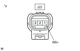
| z22-1 (RR+) - Body ground | Engine switch on (IG) | 11 to 14 V |
| OK | | REPLACE REAR SPEED SENSOR RH |
| NG | | REPLACE BRAKE ACTUATOR ASSEMBLY |
| 14. | INSPECT REAR SKID CONTROL SENSOR WIRE RH NO. 1 |
| (a) Turn the engine switch off. |
|
(b) Make sure that there is no looseness at the locking part and the connecting part of the connectors.
OK:
The connector is securely connected.
(c) Disconnect the j1 and j5 rear skid control sensor wire RH No. 1 connector.
(d) Check both the connector case and the terminals for deformation and corrosion.
OK:
No deformation or corrosion.
(e) Measure the resistance according to the value(s) in the table below.
Standard Resistance:
| Tester Connection | Condition | Specified Condition |
|---|---|---|
| j1-2 (RR+) - j5-1 (RR+) | Always | Below 1 Ω |
| j1-2 (RR+) or j5-1 (RR+) - Body ground and other terminals | Always | 10 kΩ or higher |
| j1-1 (RR-) - j5-3 (RR-) | Always | Below 1 Ω |
| j1-1 (RR-) or j5-3 (RR-) - Body ground and other terminals | Always | 10 kΩ or higher |
| NG | | REPLACE REAR SKID CONTROL SENSOR WIRE RH NO. 1 |
|
| 15. | INSPECT REAR SKID CONTROL SENSOR WIRE RH NO. 2 |
| (a) Make sure that there is no looseness at the locking part and the connecting part of the connectors. OK: The connector is securely connected. |
|
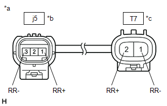
(b) Disconnect the T7 rear skid control sensor wire RH No. 2 connector.
(c) Check both the connector case and the terminals for deformation and corrosion.
OK:
No deformation or corrosion.
(d) Measure the resistance according to the value(s) in the table below.
Standard Resistance:
| Tester Connection | Condition | Specified Condition |
|---|---|---|
| j5-1 (RR+) - T7-2 (RR+) | Always | Below 1 Ω |
| j5-1 (RR+) or T7-2 (RR+) - Body ground and other terminals | Always | 10 kΩ or higher |
| j5-3 (RR-) - T7-1 (RR-) | Always | Below 1 Ω |
| j5-3 (RR-) or T7-1 (RR-) - Body ground and other terminals | Always | 10 kΩ or higher |
| NG | | REPLACE REAR SKID CONTROL SENSOR WIRE RH NO. 2 |
|
| 16. | CHECK HARNESS AND CONNECTOR (REAR SKID CONTROL SENSOR WIRE RH NO. 2 - BRAKE ACTUATOR ASSEMBLY) |
(a) Make sure that there is no looseness at the locking part and the connecting part of the connectors.
OK:
The connector is securely connected.
(b) Disconnect the A41 skid control ECU (brake actuator assembly) connector.
(c) Check both the connector case and the terminals for deformation and corrosion.
OK:
No deformation or corrosion.
(d) Measure the resistance according to the value(s) in the table below.
Standard Resistance:
| Tester Connection | Condition | Specified Condition |
|---|---|---|
| T7-2 (RR+) - A41-20 (RR+) | Always | Below 1 Ω |
| T7-2 (RR+) or A41-20 (RR+) - Body ground | Always | 10 kΩ or higher |
| T7-1 (RR-) - A41-19 (RR-) | Always | Below 1 Ω |
| T7-1 (RR-) or A41-19 (RR-) - Body ground | Always | 10 kΩ or higher |
| NG | | REPAIR OR REPLACE HARNESS OR CONNECTOR |
|
| 17. | INSPECT BRAKE ACTUATOR ASSEMBLY (SENSOR POWER SOURCE CIRCUIT) |
| (a) Reconnect the A41 skid control ECU (brake actuator assembly) connector. |
|
(b) Reconnect the j5 and T7 rear skid control sensor wire RH No. 2 connector.
(c) Make sure that there is no looseness at the locking part and the connecting part of the connectors.
OK:
The connector is securely connected.
(d) Turn the engine switch on (IG).
(e) Measure the voltage according to the value(s) in the table below.
Standard Voltage:
| Tester Connection | Condition | Specified Condition |
|---|---|---|
| j1-2 (RR+) - Body ground | Engine switch on (IG) | 11 to 14 V |
HINT:
The rear speed sensor RH is incorporated into the rear axle hub and bearing assembly RH.
If the rear speed sensor RH needs to be replaced, replace the rear axle hub and bearing assembly RH.
| OK | | REPLACE REAR AXLE HUB AND BEARING ASSEMBLY RH |
| NG | | REPLACE BRAKE ACTUATOR ASSEMBLY |
 Right Rear Wheel Speed Sensor Circuit Short to Battery (C051212)
DESCRIPTION Refer to DTC C05121F. Click here DTC No. Detection Item DTC Detection Condition Trouble Area C051212 Right Rear Wheel Speed Sensor Circuit Short to Battery The speed sen ...
 Right Rear Wheel Speed Sensor Circuit Intermittent (C05121F)
DESCRIPTION The speed sensor detects wheel speed and sends the appropriate signals to the skid control ECU (brake actuator assembly). These signals are used for brake control. Speed sensor rotors have ...
Other materials:
Lexus RX (RX 350L, RX450h) 2016-2025 Repair Manual > Automatic Transaxle System: Input/Turbine Speed Sensor "B" Circuit Short to Battery (P276512,P276514,P276531)
DESCRIPTION The transmission revolution sensor (NC3) detects the automatic transmission No. 3 clutch drum rotation speed. DTC No. Detection Item DTC Detection Condition Trouble Area MIL Memory Note P276512 Input/Turbine Speed Sensor "B" Circuit Short to Battery 1. Diagnosis Co ...
Lexus RX (RX 350L, RX450h) 2016-2025 Repair Manual > Sfi System: Internal Control Module EEPROM Data Memory Failure (P062F44)
DESCRIPTION The ECM monitors its internal operation and stores this DTC when it detects an internal malfunction. DTC No. Detection Item DTC Detection Condition Trouble Area MIL Memory Note P062F44 Internal Control Module EEPROM Data Memory Failure An ECM internal error (EEPROM ...
Lexus RX (RX 350L, RX450h) 2016-{YEAR} Owners Manual
- For your information
- Pictorial index
- For safety and security
- Instrument cluster
- Operation of each component
- Driving
- Lexus Display Audio system
- Interior features
- Maintenance and care
- When trouble arises
- Vehicle specifications
- For owners
Lexus RX (RX 350L, RX450h) 2016-{YEAR} Repair Manual

0.0153