Lexus RX (RX 350L, RX450h) 2016-2026 Repair Manual: Right Rear Wheel Speed Sensor Circuit Intermittent (C05121F)
DESCRIPTION
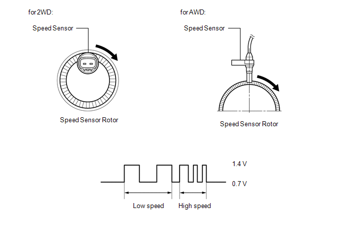
The speed sensor detects wheel speed and sends the appropriate signals to the skid control ECU (brake actuator assembly). These signals are used for brake control.
Speed sensor rotors have rows of alternating N and S magnetic poles, and their magnetic fields change when the rotors turn.
Each speed sensor detects that magnetic change and sends a pulse signal to the skid control ECU (brake actuator assembly).
HINT:
When the connectors between the speed sensor and skid control ECU (brake actuator assembly) are connected, the following waveform is output.
| DTC No. | Detection Item | DTC Detection Condition | Trouble Area |
|---|---|---|---|
| C05121F | Right Rear Wheel Speed Sensor Circuit Intermittent | Any of the following is detected:
|
|
- *1: for AWD
- *2: for 2WD
- *3: w/ AVS
| Vehicle Condition | ||||
|---|---|---|---|---|
| Pattern 1 | Pattern 2 | Pattern 3 | ||
| Diagnosis Condition | When the +BS terminal voltage is 17.4 V or less | ○ | - | - |
| When the +BS terminal voltage is 17.4 V or less at a vehicle speed of 10 km/h (6 mph) or more | - | - | ○ | |
| When the +BS terminal voltage is 17.4 V or less at a vehicle speed of 20 km/h (12 mph) or more | - | ○ | - | |
| Malfunction Status | An open in the sensor signal circuit of a malfunctioning area occurs 255 times or more | ○ | - | - |
| Noise occurs in the sensor signals of a malfunctioning wheel 75 times or more within 5 seconds | - | ○ | - | |
| Noise occurs once per rotor rotation | - | - | ○ | |
| Detection Time | - | - | 15 seconds or more | |
| Number of Trips | 1 trip | 1 trip | 1 trip | |
HINT:
DTC will be output when conditions for any of the patterns in the table above are met.
WIRING DIAGRAM
w/o AVS (for AWD)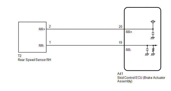 w/o AVS (for 2WD)
 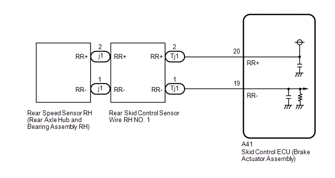 w/ AVS (for AWD)
 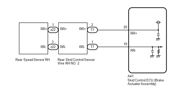 w/ AVS (for 2WD)
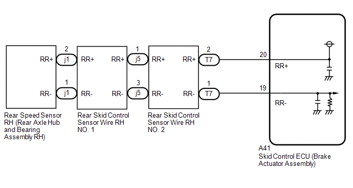
CAUTION / NOTICE / HINT
NOTICE:
-
After replacing the skid control ECU (brake actuator assembly), perform "Calibration".
Click here
.gif)
-
After replacing or removing and installing a speed sensor, perform Dealer Mode (Signal Check) inspection to confirm that the speed sensors are operating correctly.
Click here
-
After replacing or removing and installing a speed sensor rotor, perform Dealer Mode (Signal Check) inspection to confirm that the speed sensors are operating correctly.
Click here
PROCEDURE
| 1. | READ VALUE USING TECHSTREAM (MOMENTARY INTERRUPTION) |
(a) Connect the Techstream to the DLC3.
(b) Turn the engine switch on (IG).
(c) Enter the following menus: Chassis / Brake/EPB / Data List.
Chassis > Brake/EPB > Data List| Tester Display | Measurement Item | Range | Normal Condition | Diagnostic Note |
|---|---|---|---|---|
| RR Speed Sensor Voltage Open | Rear speed sensor RH voltage open detection | Under intermittent / Normal | Under intermittent: Momentary interruption detected Normal: Momentary interruption not detected | - |
| Tester Display |
|---|
| RR Speed Sensor Voltage Open |
(d) Select the line graph display.
(e) Check for any momentary interruption in the wire harness and connector.
Click here
OK:
Normal (There are no momentary interruptions.)
NOTICE:
Perform the above inspection before removing the sensor and connector.
| NG | .gif) | GO TO STEP 5 |
|
.gif)
| 2. | READ VALUE USING TECHSTREAM (RR WHEEL SPEED) |
(a) Enter the following menus: Chassis / Brake/EPB / Data List.
Chassis > Brake/EPB > Data List| Tester Display | Measurement Item | Range | Normal Condition | Diagnostic Note |
|---|---|---|---|---|
| RR Wheel Speed | Rear wheel speed sensor RH reading | Min.: 0.0 km/h (0.0 mph) Max.: 6553.5 km/h (4072 mph) | Vehicle stopped: 0.0 km/h (0.0 mph) | When driving at constant speed: No large fluctuations |
| Tester Display |
|---|
| RR Wheel Speed |
(b) Start the engine.
(c) Perform a road test.
(d) Check the speed value output from the speed sensor displayed on the Techstream.
HINT:
Factors that affect the indicated vehicle speed include tire size, tire pressure, and tire wear. The speed indicated on the speedometer has an allowable margin of error. This can be tested using a speedometer tester (calibrated chassis dynamometer). For details about testing and the margin of error, see the reference chart.
Click here
OK:
The speed value output from the speed sensor displayed on the Techstream is similar to the speed indicated on the speedometer.
| NG | | GO TO STEP 5 |
|
| 3. | CLEAR DTC |
(a) Operate the Techstream to clear the codes. Enter the following menus: Chassis / Brake/EPB / Trouble Codes.
Chassis > Brake/EPB > Clear DTCs(b) Press the DTC clear button.
(c) Turn the engine switch off.
|
| 4. | RECONFIRM DTC |
(a) Start the engine.
(b) Perform a road test.
(c) Read the DTCs following the prompts on the Techstream. Enter the following menus: Chassis / Brake/EPB / Trouble Codes.
Chassis > Brake/EPB > Trouble Codes(d) Check if the same DTC is output.
| Result | Proceed to |
|---|---|
| DTC C05121F is not output. | A |
| DTC C05121F is output. | B |
| A | | USE SIMULATION METHOD TO CHECK |
| B | | REPLACE BRAKE ACTUATOR ASSEMBLY |
| 5. | CHECK VEHICLE SPECIFICATION |
(a) Check the vehicle specification.
| Result | Proceed to |
|---|---|
| for AWD | A |
| for 2WD | B |
| B | | GO TO STEP 14 |
|
| 6. | CHECK REAR SPEED SENSOR RH INSTALLATION |
| (a) Turn the engine switch off. |
|
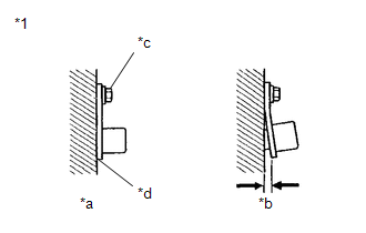
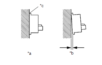
(b) Check the rear speed sensor RH installation.
OK:
There is no clearance between the rear speed sensor RH and rear axle carrier sub-assembly RH.
The installation bolt is tightened properly.
Torque
8.5 N*m (87 kgf*cm, 75 in.*lbf)
| NG | | REINSTALL OR REPLACE REAR SPEED SENSOR RH |
|
| 7. | CHECK REAR SPEED SENSOR RH AND REAR SPEED SENSOR ROTOR RH (CHECK FOR FOREIGN MATTER) |
(a) Remove the rear speed sensor RH and the component with the rear speed sensor rotor RH.
for rear speed sensor RH: Click here
for rear speed sensor rotor RH: Click here
(b) Check the rear speed sensor RH tip and rear speed sensor rotor RH.
OK:
No scratches, oil, or foreign matter on the rear speed sensor RH tip and rear speed sensor rotor RH.
NOTICE:
- If there is oil or foreign matter on the rear speed sensor RH, clean the rear speed sensor RH.
- If the rear speed sensor RH is damaged, replace the rear speed sensor RH with a new one.
- Do not use parts cleaner when cleaning the rear speed sensor rotor RH.
- If the rear speed sensor rotor RH is damaged, replace the rear speed sensor rotor RH with a new one.
HINT:
- The rear speed sensor rotor RH is incorporated into the rear axle hub and bearing assembly RH.
- If the rear speed sensor rotor RH needs to be replaced, replace it together with the rear axle hub and bearing assembly RH.
| NG | | CLEAN OR REPLACE REAR SPEED SENSOR RH OR COMPONENT WITH REAR SENSOR ROTOR RH |
|
| 8. | CHECK VEHICLE SPECIFICATION |
(a) Check the vehicle specification.
| Result | Proceed to |
|---|---|
| w/o AVS | A |
| w/ AVS | B |
| B | | GO TO STEP 11 |
|
| 9. | CHECK HARNESS AND CONNECTOR (REAR SPEED SENSOR RH - BRAKE ACTUATOR ASSEMBLY) |
(a) Make sure that there is no looseness at the locking part and the connecting part of the connectors.
OK:
The connector is securely connected.
(b) Disconnect the A41 skid control ECU (brake actuator assembly) connector.
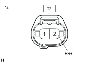
(c) Disconnect the T2 rear speed sensor RH connector.
(d) Check both the connector case and the terminals for deformation and corrosion.
OK:
No deformation or corrosion.
(e) Measure the resistance according to the value(s) in the table below.
Standard Resistance:
| Tester Connection | Condition | Specified Condition |
|---|---|---|
| T2-2 (RR+) - A41-20 (RR+) | Always | Below 1 Ω |
| T2-2 (RR+) or A41-20 (RR+) - Body ground | Always | 10 kΩ or higher |
| T2-1 (RR-) - A41-19 (RR-) | Always | Below 1 Ω |
| T2-1 (RR-) or A41-19 (RR-) - Body ground | Always | 10 kΩ or higher |
| NG | | REPAIR OR REPLACE HARNESS OR CONNECTOR |
|
| 10. | INSPECT BRAKE ACTUATOR ASSEMBLY (SENSOR POWER SOURCE CIRCUIT) |
| (a) Reconnect the A41 skid control ECU (brake actuator assembly) connector. |
|
(b) Make sure that there is no looseness at the locking part and the connecting part of the connectors.
OK:
The connector is securely connected.
(c) Turn the engine switch on (IG).
(d) Measure the voltage according to the value(s) in the table below.
Standard Voltage:
| Tester Connection | Condition | Specified Condition |
|---|---|---|
| T2-2 (RR+) - Body ground | Engine switch on (IG) | 11 to 14 V |
| OK | | REPLACE REAR SPEED SENSOR RH |
| NG | | REPLACE BRAKE ACTUATOR ASSEMBLY |
| 11. | INSPECT REAR SKID CONTROL SENSOR WIRE RH NO. 2 |
| (a) Make sure that there is no looseness at the locking part and the connecting part of the connectors. OK: The connector is securely connected. |
|
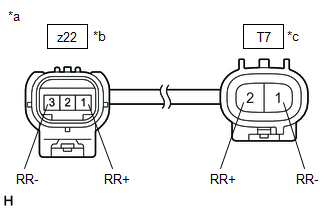
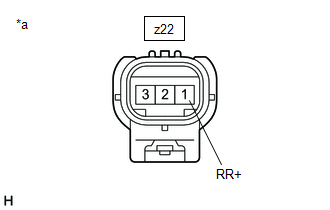
(b) Disconnect the z22 and T7 rear skid control sensor wire RH No. 2 connector.
(c) Check both the connector case and the terminals for deformation and corrosion.
OK:
No deformation or corrosion.
(d) Measure the resistance according to the value(s) in the table below.
Standard Resistance:
| Tester Connection | Condition | Specified Condition |
|---|---|---|
| z22-1 (RR+) - T7-2 (RR+) | Always | Below 1 Ω |
| z22-1 (RR+) or T7-2 (RR+) - Body ground and other terminals | Always | 10 kΩ or higher |
| z22-3 (RR-) - T7-1 (RR-) | Always | Below 1 Ω |
| z22-3 (RR-) or T7-1 (RR-) - Body ground and other terminals | Always | 10 kΩ or higher |
| NG | | REPLACE REAR SKID CONTROL SENSOR WIRE RH NO. 2 |
|
| 12. | INSPECT HARNESS AND CONNECTOR (REAR SKID CONTROL SENSOR WIRE RH NO. 2 - BRAKE ACTUATOR ASSEMBLY) |
(a) Make sure that there is no looseness at the locking part and the connecting part of the connectors.
OK:
The connector is securely connected.
(b) Disconnect the A41 skid control ECU (brake actuator assembly) connector.
(c) Check both the connector case and the terminals for deformation and corrosion.
OK:
No deformation or corrosion.
(d) Measure the resistance according to the value(s) in the table below.
Standard Resistance:
| Tester Connection | Condition | Specified Condition |
|---|---|---|
| T7-2 (RR+) - A41-20 (RR+) | Always | Below 1 Ω |
| T7-2 (RR+) or A41-20 (RR+) - Body ground | Always | 10 kΩ or higher |
| T7-1 (RR-) - A41-19 (RR-) | Always | Below 1 Ω |
| T7-1 (RR-) or A41-19 (RR-) - Body ground | Always | 10 kΩ or higher |
| NG | | REPAIR OR REPLACE HARNESS OR CONNECTOR |
|
| 13. | INSPECT BRAKE ACTUATOR ASSEMBLY (SENSOR POWER SOURCE CIRCUIT) |
| (a) Reconnect the A41 skid control ECU (brake actuator assembly) connector. |
|
(b) Reconnect the T7 rear skid control sensor wire RH No. 2 connector.
(c) Make sure that there is no looseness at the locking part and the connecting part of the connectors.
OK:
The connector is securely connected.
(d) Turn the engine switch on (IG).
(e) Measure the voltage according to the value(s) in the table below.
Standard Voltage:
| Tester Connection | Condition | Specified Condition |
|---|---|---|
| z22-1 (RR+) - Body ground | Engine switch on (IG) | 11 to 14 V |
| OK | | REPLACE REAR SPEED SENSOR RH |
| NG | | REPLACE BRAKE ACTUATOR ASSEMBLY |
| 14. | CHECK REAR SPEED SENSOR RH INSTALLATION |
| (a) Turn the engine switch off. |
|
(b) Check the rear speed sensor RH installation.
OK:
There is no clearance between the rear speed sensor RH and the rear axle hub and bearing assembly RH.
HINT:
The rear speed sensor rotor RH and rear speed sensor RH are incorporated into the rear axle hub and bearing assembly RH.
If the rear speed sensor rotor RH needs to be replaced, replace the rear axle hub and bearing assembly RH with rear speed sensor RH.
| NG | | REPLACE REAR AXLE HUB AND BEARING ASSEMBLY RH |
|
| 15. | CHECK VEHICLE SPECIFICATION |
(a) Check the vehicle specification.
| Result | Proceed to |
|---|---|
| w/o AVS | A |
| w/ AVS | B |
| B | | GO TO STEP 19 |
|
| 16. | INSPECT REAR SKID CONTROL SENSOR WIRE RH NO. 1 |
| (a) Make sure that there is no looseness at the locking part and the connecting part of the connectors. OK: The connector is securely connected. |
|
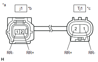
(b) Disconnect the j1 and Tj1 rear skid control sensor wire RH No. 1 connector.
(c) Check both the connector case and the terminals for deformation and corrosion.
OK:
No deformation or corrosion.
(d) Measure the resistance according to the value(s) in the table below.
Standard Resistance:
| Tester Connection | Condition | Specified Condition |
|---|---|---|
| j1-2 (RR+) - Tj1-2 (RR+) | Always | Below 1 Ω |
| j1-2 (RR+) or Tj1-2 (RR+) - Body ground and other terminals | Always | 10 kΩ or higher |
| j1-1 (RR-) - Tj1-1 (RR-) | Always | Below 1 Ω |
| j1-1 (RR-) or Tj1-1 (RR-) - Body ground and other terminals | Always | 10 kΩ or higher |
| NG | | REPLACE REAR SKID CONTROL SENSOR WIRE RH NO. 1 |
|
| 17. | CHECK HARNESS AND CONNECTOR (REAR SKID CONTROL SENSOR WIRE RH NO. 1 - BRAKE ACTUATOR ASSEMBLY) |
(a) Make sure that there is no looseness at the locking part and the connecting part of the connectors.
OK:
The connector is securely connected.
(b) Disconnect the A41 skid control ECU (brake actuator assembly) connector.
(c) Check both the connector case and the terminals for deformation and corrosion.
OK:
No deformation or corrosion.
(d) Measure the resistance according to the value(s) in the table below.
Standard Resistance:
| Tester Connection | Condition | Specified Condition |
|---|---|---|
| Tj1-2 (RR+) - A41-20 (RR+) | Always | Below 1 Ω |
| Tj1-2 (RR+) or A41-20 (RR+) - Body ground | Always | 10 kΩ or higher |
| Tj1-1 (RR-) - A41-19 (RR-) | Always | Below 1 Ω |
| Tj1-1 (RR-) or A41-19 (RR-) - Body ground | Always | 10 kΩ or higher |
| NG | | REPAIR OR REPLACE HARNESS OR CONNECTOR |
|
| 18. | INSPECT BRAKE ACTUATOR ASSEMBLY (SENSOR POWER SOURCE CIRCUIT) |
| (a) Reconnect the A41 skid control ECU (brake actuator assembly) connector. |
|

(b) Reconnect the Tj1 rear skid control sensor wire RH No. 1 connector.
(c) Make sure that there is no looseness at the locking part and the connecting part of the connectors.
OK:
The connector is securely connected.
(d) Turn the engine switch on (IG).
(e) Measure the voltage according to the value(s) in the table below.
Standard Voltage:
| Tester Connection | Condition | Specified Condition |
|---|---|---|
| j1-2 (RR+) - Body ground | Engine switch on (IG) | 11 to 14 V |
HINT:
The rear speed sensor RH is incorporated into the rear axle hub and bearing assembly RH.
If the rear speed sensor RH needs to be replaced, replace the rear axle hub and bearing assembly RH.
| OK | | REPLACE REAR AXLE HUB AND BEARING ASSEMBLY RH |
| NG | | REPLACE BRAKE ACTUATOR ASSEMBLY |
| 19. | INSPECT REAR SKID CONTROL SENSOR WIRE RH NO. 1 |
| (a) Turn the engine switch off. |
|
(b) Make sure that there is no looseness at the locking part and the connecting part of the connectors.
OK:
The connector is securely connected.
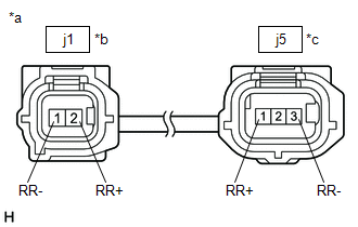
(c) Disconnect the j1 and j5 rear skid control sensor wire RH No. 1 connector.
(d) Check both the connector case and the terminals for deformation and corrosion.
OK:
No deformation or corrosion.
(e) Measure the resistance according to the value(s) in the table below.
Standard Resistance:
| Tester Connection | Condition | Specified Condition |
|---|---|---|
| j1-2 (RR+) - j5-1 (RR+) | Always | Below 1 Ω |
| j1-2 (RR+) or j5-1 (RR+) - Body ground and other terminals | Always | 10 kΩ or higher |
| j1-1 (RR-) - j5-3 (RR-) | Always | Below 1 Ω |
| j1-1 (RR-) or j5-3 (RR-) - Body ground and other terminals | Always | 10 kΩ or higher |
| NG | | REPLACE REAR SKID CONTROL SENSOR WIRE RH NO. 1 |
|
| 20. | INSPECT REAR SKID CONTROL SENSOR WIRE RH NO. 2 |
| (a) Make sure that there is no looseness at the locking part and the connecting part of the connectors. OK: The connector is securely connected. |
|
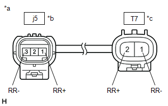
(b) Disconnect the T7 rear skid control sensor wire RH No. 2 connector.
(c) Check both the connector case and the terminals for deformation and corrosion.
OK:
No deformation or corrosion.
(d) Measure the resistance according to the value(s) in the table below.
Standard Resistance:
| Tester Connection | Condition | Specified Condition |
|---|---|---|
| j5-1 (RR+) - T7-2 (RR+) | Always | Below 1 Ω |
| j5-1 (RR+) or T7-2 (RR+) - Body ground and other terminals | Always | 10 kΩ or higher |
| j5-3 (RR-) - T7-1 (RR-) | Always | Below 1 Ω |
| j5-3 (RR-) or T7-1 (RR-) - Body ground and other terminals | Always | 10 kΩ or higher |
| NG | | REPLACE REAR SKID CONTROL SENSOR WIRE RH NO. 2 |
|
| 21. | CHECK HARNESS AND CONNECTOR (REAR SKID CONTROL SENSOR WIRE RH NO. 2 - BRAKE ACTUATOR ASSEMBLY) |
(a) Make sure that there is no looseness at the locking part and the connecting part of the connectors.
OK:
The connector is securely connected.
(b) Disconnect the A41 skid control ECU (brake actuator assembly) connector.
(c) Check both the connector case and the terminals for deformation and corrosion.
OK:
No deformation or corrosion.
(d) Measure the resistance according to the value(s) in the table below.
Standard Resistance:
| Tester Connection | Condition | Specified Condition |
|---|---|---|
| T7-2 (RR+) - A41-20 (RR+) | Always | Below 1 Ω |
| T7-2 (RR+) or A41-20 (RR+) - Body ground | Always | 10 kΩ or higher |
| T7-1 (RR-) - A41-19 (RR-) | Always | Below 1 Ω |
| T7-1 (RR-) or A41-19 (RR-) - Body ground | Always | 10 kΩ or higher |
| NG | | REPAIR OR REPLACE HARNESS OR CONNECTOR |
|
| 22. | INSPECT BRAKE ACTUATOR ASSEMBLY (SENSOR POWER SOURCE CIRCUIT) |
| (a) Reconnect the A41 skid control ECU (brake actuator assembly) connector. |
|
(b) Reconnect the j5 and T7 rear skid control sensor wire RH No. 2 connector.
(c) Make sure that there is no looseness at the locking part and the connecting part of the connectors.
OK:
The connector is securely connected.
(d) Turn the engine switch on (IG).
(e) Measure the voltage according to the value(s) in the table below.
Standard Voltage:
| Tester Connection | Condition | Specified Condition |
|---|---|---|
| j1-2 (RR+) - Body ground | Engine switch on (IG) | 11 to 14 V |
HINT:
The rear speed sensor RH is incorporated into the rear axle hub and bearing assembly RH.
If the rear speed sensor RH needs to be replaced, replace the rear axle hub and bearing assembly RH.
| OK | | REPLACE REAR AXLE HUB AND BEARING ASSEMBLY RH |
| NG | | REPLACE BRAKE ACTUATOR ASSEMBLY |
 Right Rear Wheel Speed Sensor Circuit Short to Ground or Open (C051214)
DESCRIPTION Refer to DTC C05121F. Click here DTC No. Detection Item DTC Detection Condition Trouble Area C051214 Right Rear Wheel Speed Sensor Circuit Short to Ground or Open An ope ...
 Multi-axis Acceleration Sensor Module "A" Missing Calibration (C051D54,C121054)
DESCRIPTION for Optitron Meter Type:
The airbag sensor assembly has a built-in yaw rate and acceleration sensor and detects the vehicle condition.
The skid control ECU (brake actuator assembly) rec ...
Other materials:
Lexus RX (RX 350L, RX450h) 2016-2026 Repair Manual > Oil Pump: Removal
REMOVAL CAUTION / NOTICE / HINT The necessary procedures (adjustment, calibration, initialization, or registration) that must be performed after parts are removed and installed, or replaced during engine unit removal/installation are shown below. Necessary Procedure After Parts Removed/Installed/Rep ...
Lexus RX (RX 350L, RX450h) 2016-2026 Repair Manual > Lighting (ext): Relay
On-vehicle InspectionON-VEHICLE INSPECTION PROCEDURE 1. INSPECT H-LP LH RELAY (a) Measure the resistance according to the value(s) in the table below. Standard Resistance: Tester Connection Condition Specified Condition 3 - 5 Voltage not applied between terminals 1 and 2 10 kΩ or ...
Lexus RX (RX 350L, RX450h) 2016-{YEAR} Owners Manual
- For your information
- Pictorial index
- For safety and security
- Instrument cluster
- Operation of each component
- Driving
- Lexus Display Audio system
- Interior features
- Maintenance and care
- When trouble arises
- Vehicle specifications
- For owners
Lexus RX (RX 350L, RX450h) 2016-{YEAR} Repair Manual

0.0593