Lexus RX (RX 350L, RX450h) 2016-2024 Repair Manual: Air Outlet Damper Control Servo Motor Circuit(Driver Side Front A/C Rear Air Flow) (B1486/86)
DESCRIPTION
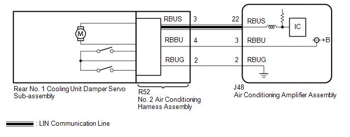
The Rear No. 1 cooling unit damper servo sub-assembly sends pulse signals to inform the air conditioning amplifier assembly of the damper position. The air conditioning amplifier assembly activates the motor (normal or reverse) based on these signals to move the Rear No. 1 cooling unit damper servo sub-assembly to the appropriate position, which controls the air outlet switching.
The air conditioning amplifier assembly communicates with the servo through a communication/driver IC and wiring assembly called the No. 2 air conditioning harness assembly.
| DTC No. | Detection Item | DTC Detection Condition | Trouble Area | Memory |
|---|---|---|---|---|
| B1486/86 | Air Outlet Damper Control Servo Motor Circuit(Driver Side Front A/C Rear Air Flow) | Rear air outlet damper position sensor value does not change even if air conditioning amplifier assembly operates Rear No. 1 cooling unit damper servo sub-assembly |
| Memorized (30 sec. or more)* |
- *: The air conditioning amplifier assembly stores this DTC if the malfunction has occurred for the period of time indicated in the brackets.
WIRING DIAGRAM
CAUTION / NOTICE / HINT
HINT:
Confirm that no mechanical problems are present because this DTC can be output when either a damper link or damper is mechanically locked.
PROCEDURE
| 1. | READ VALUE USING TECHSTREAM |
(a) Connect the Techstream to the DLC3.
(b) Turn the engine switch on (IG).
(c) Turn the Techstream on.
(d) Operate the rear passenger side mode switch.
(e) Enter the following menus: Body Electrical / Air Conditioner / Data List.
(f) Check the value(s) by referring to the table below.
Body Electrical > Air Conditioner > Data List| Tester Display | Measurement Item | Range | Normal Condition | Diagnostic Note |
|---|---|---|---|---|
| Air Outlet Servo Pls (F&R D) | Rear No. 1 cooling unit damper servo sub-assembly target pulse | Min.: 128 Max.: 383 |
| - |
| A/O Servo Actual Pulse(F&R D) | Rear No. 1 cooling unit damper servo sub-assembly actual pulse | Min.: 128 Max.: 383 |
| - |
| Tester Display |
|---|
| Air Outlet Servo Pls (F&R D) |
| A/O Servo Actual Pulse(F&R D) |
OK:
When the rear passenger side mode switch is operated, the actual pulse changes following the target pulse.
| Result | Proceed to |
|---|---|
| Target pulse changes but actual pulse does not change | A |
| Target pulse and actual pulse do not change | B |
| Actual pulse changes following the target pulse (When troubleshooting according to the DTC) | C |
| Actual pulse changes following the target pulse (When troubleshooting according to Problem Symptoms Table) | D |
| B | .gif) | REPLACE AIR CONDITIONING AMPLIFIER ASSEMBLY |
| C | | GO TO STEP 5 |
| D | | PROCEED TO NEXT SUSPECTED AREA SHOWN IN PROBLEM SYMPTOMS TABLE |
|
.gif)
| 2. | CHECK HARNESS AND CONNECTOR (NO. 2 AIR CONDITIONING HARNESS ASSEMBLY - AIR CONDITIONING AMPLIFIER ASSEMBLY) |
(a) Disconnect the R52 No. 2 air conditioning harness assembly connector.
(b) Disconnect the J48 air conditioning amplifier assembly connector.
(c) Measure the resistance according to the value(s) in the table below.
Standard Resistance:
| Tester Connection | Condition | Specified Condition |
|---|---|---|
| R52-4 (RBBU) - J48-3 (RBBU) | Always | Below 1 Ω |
| R52-3 (RBUS) - J48-22 (RBUS) | Always | Below 1 Ω |
| R52-2 (RBUG) - J48-2 (RBUG) | Always | Below 1 Ω |
| R52-4 (RBBU) or J48-3 (RBBU) - Other terminals and body ground | Always | 10 kΩ or higher |
| R52-3 (RBUS) or J48-22 (RBUS) - Other terminals and body ground | Always | 10 kΩ or higher |
| R52-2 (RBUG) or J48-2 (RBUG) - Other terminals and body ground | Always | 10 kΩ or higher |
| NG | | REPAIR OR REPLACE HARNESS OR CONNECTOR |
|
| 3. | CHECK REAR NO. 1 COOLING UNIT DAMPER SERVO SUB-ASSEMBLY |
(a) Replace the Rear No. 1 cooling unit damper servo sub-assembly.
Click here .gif)
HINT:
Since the servo motor cannot be inspected while it is removed from the vehicle, replace the servo motor with a new or known good one and check that the condition returns to normal.
(b) Connect the Techstream to the DLC3.
(c) Turn the engine switch on (IG).
(d) Turn the Techstream on.
(e) Enter the following menus: Body Electrical / Air Conditioner / Trouble Codes.
(f) Clear the DTC.
Body Electrical > Air Conditioner > Clear DTCs(g) Check for DTCs.
Body Electrical > Air Conditioner > Trouble CodesOK:
DTC B1486/86 is not output.
| NG | | END (REAR NO. 1 COOLING UNIT DAMPER SERVO SUB-ASSEMBLY WAS DEFECTIVE) |
|
| 4. | CHECK NO. 2 AIR CONDITIONING HARNESS ASSEMBLY |
(a) Replace the No. 2 air conditioning harness assembly.
Click here
HINT:
Since the No. 2 air conditioning harness assembly cannot be inspected while it is removed from the vehicle, replace the No. 2 air conditioning harness assembly with a new or known good one and check that the condition returns to normal.
(b) Connect the Techstream to the DLC3.
(c) Turn the engine switch on (IG).
(d) Turn the Techstream on.
(e) Enter the following menus: Body Electrical / Air Conditioner / Trouble Codes.
(f) Clear the DTC.
Body Electrical > Air Conditioner > Clear DTCs(g) Check for DTCs.
Body Electrical > Air Conditioner > Trouble CodesOK:
DTC B1486/86 is not output.
| OK | | REPLACE AIR CONDITIONING AMPLIFIER ASSEMBLY |
| NG | | END (NO. 2 AIR CONDITIONING HARNESS ASSEMBLY WAS DEFECTIVE) |
| 5. | RECONFIRM DTC OUTPUT |
(a) Connect the Techstream to the DLC3.
(b) Turn the engine switch on (IG).
(c) Turn the Techstream on.
(d) Enter the following menus: Body Electrical / Air Conditioner / Trouble Codes.
(e) Check for DTCs.
Body Electrical > Air Conditioner > Trouble Codes| Result | Proceed to |
|---|---|
| DTC B1486/86 is output | A |
| DTC B1486/86 is not output | B |
| A | | REPLACE AIR CONDITIONING AMPLIFIER ASSEMBLY |
| B | | USE SIMULATION METHOD TO CHECK |
 Emission Gas NOx Sensor Circuit (B1461/61)
DESCRIPTION The smog ventilation sensor is installed to the front of the cooler condenser assembly to automatically control the air inlet mode (fresh, recirculation/fresh, and recirculation). This sen ...
 BUS IC Communication Malfunction (B1497/97)
DESCRIPTION Front Air Conditioning System The air conditioning harness assembly connects the air conditioning amplifier assembly and the servo motors. The air conditioning amplifier assembly supplies ...
Other materials:
Lexus RX (RX 350L, RX450h) 2016-2024 Repair Manual > Automatic Transaxle Fluid: Replacement
REPLACEMENT PROCEDURE 1. REMOVE FRONT WHEEL OPENING EXTENSION PAD LH Click here 2. REMOVE NO. 3 ENGINE UNDER COVER Click here 3. REMOVE FRONT FENDER APRON SEAL LH Click here 4. REPLACE AUTOMATIC TRANSAXLE FLUID (a) Lift the vehicle. [#1] NOTICE: Set the vehicle on a lift so that the v ...
Lexus RX (RX 350L, RX450h) 2016-2024 Repair Manual > Propeller Shaft Assembly: Reassembly
REASSEMBLY CAUTION / NOTICE / HINT NOTICE:
When using a vise, place aluminum plates between the part and vise.
When using a vise, do not overtighten it.
PROCEDURE 1. INSTALL CENTER NO. 2 SUPPORT BEARING ASSEMBLY (for Front Side) (a) Set the center No. 2 support bearing assembly on the interm ...
Lexus RX (RX 350L, RX450h) 2016-{YEAR} Owners Manual
- For your information
- Pictorial index
- For safety and security
- Instrument cluster
- Operation of each component
- Driving
- Lexus Display Audio system
- Interior features
- Maintenance and care
- When trouble arises
- Vehicle specifications
- For owners
Lexus RX (RX 350L, RX450h) 2016-{YEAR} Repair Manual

0.0179