Lexus RX (RX 350L, RX450h) 2016-2026 Repair Manual: Emission Gas NOx Sensor Circuit (B1461/61)
DESCRIPTION
The smog ventilation sensor is installed to the front of the cooler condenser assembly to automatically control the air inlet mode (fresh, recirculation/fresh, and recirculation).
This sensor detects NOx in the ambient air and transmits signals to the air conditioning amplifier assembly.
| DTC No. | Detection Item | DTC Detection Condition | Trouble Area | Memory |
|---|---|---|---|---|
| B1461/61 | Emission Gas NOx Sensor Circuit | Open or short in emission gas NOx sensor circuit (w/ Smog Ventilation Sensor) |
| - |
WIRING DIAGRAM
.png)
CAUTION / NOTICE / HINT
NOTICE:
- Inspect the fuses for circuits related to this system before performing the following procedure.
- If DTCs B1418/18 and B1461/61 are stored simultaneously, there may be a malfunction in the smog ventilation sensor power source circuit.
PROCEDURE
| 1. | READ VALUE USING TECHSTREAM |
(a) Connect the Techstream to the DLC3.
(b) Turn the engine switch on (IG).
(c) Turn the Techstream on.
(d) Allow exhaust gas (NOx) to travel to the sensing portion of the smog ventilation sensor.
(e) Enter the following menus: Body Electrical / Air Conditioner / Data List.
(f) Read the Data List according to the display on the Techstream.
Body Electrical > Air Conditioner > Data List| Tester Display | Measurement Item | Range | Normal Condition | Diagnostic Note |
|---|---|---|---|---|
| Emission Gas Nox Sensor | Emission gas (NOx) | Min.: 0 Max.: 255 | Smog ventilation sensor value increases as gas amount increases | - |
| Tester Display |
|---|
| Emission Gas Nox Sensor |
OK:
The display is as specified in the normal condition column.
| Result | Proceed to |
|---|---|
| NG | A |
| OK (When troubleshooting according to Problem Symptoms Table) | B |
| OK (When troubleshooting according to the DTC) | C |
| B | .gif) | PROCEED TO NEXT SUSPECTED AREA SHOWN IN PROBLEM SYMPTOMS TABLE |
.gif)
| C | | REPLACE AIR CONDITIONING AMPLIFIER ASSEMBLY |
|
.gif)
| 2. | CHECK HARNESS AND CONNECTOR (SMOG VENTILATION SENSOR - IG POWER SOURCE AND BODY GROUND) |
(a) Disconnect the A71 smog ventilation sensor connector.
(b) Measure the voltage according to the value(s) in the table below.
Standard Voltage:
| Tester Connection | Condition | Specified Condition |
|---|---|---|
| A71-3 (IG) - Body ground | Engine switch on (IG) | 11 to 14 V |
| A71-3 (IG) - Body ground | Engine switch off | Below 1 V |
(c) Measure the resistance according to the value(s) in the table below.
Standard Resistance:
| Tester Connection | Condition | Specified Condition |
|---|---|---|
| A71-6 (E) - Body ground | Always | Below 1 Ω |
| NG | | REPAIR OR REPLACE HARNESS OR CONNECTOR |
|
| 3. | CHECK HARNESS AND CONNECTOR (SMOG VENTILATION SENSOR - AIR CONDITIONING AMPLIFIER ASSEMBLY) |
(a) Disconnect the J42 air conditioning amplifier assembly connector.
(b) Measure the resistance according to the value(s) in the table below.
Standard Resistance:
| Tester Connection | Condition | Specified Condition |
|---|---|---|
| A71-1 (SG) - J42-2 (SG-2) | Always | Below 1 Ω |
| A71-4 (DGS1) - J42-27 (DGS1) | Always | Below 1 Ω |
| J42-2 (SG-2) or A71-1 (SG) - Body ground | Always | 10 kΩ or higher |
| J42-27 (DGS1) or A71-4 (DGS1) - Body ground | Always | 10 kΩ or higher |
| NG | | REPAIR OR REPLACE HARNESS OR CONNECTOR |
|
| 4. | INSPECT SMOG VENTILATION SENSOR |
| (a) Remove the smog ventilation sensor. Click here |
|
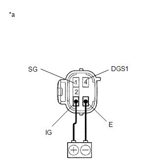
(b) Connect a positive (+) lead from the battery to terminal 3 (IG) and a negative (-) lead to terminal 6 (E).
(c) Allow exhaust gas (NOx) to travel to the sensing portion of the smog ventilation sensor, and measure the resistance between terminals 1 (SG) and 4 (DGS1).
OK:
When the sensor is exposed to exhaust gas, the resistance increases.
HINT:
The resistance of the sensor before being exposed to exhaust gas is 10 kΩ to 40 kΩ.
| OK | | REPLACE AIR CONDITIONING AMPLIFIER ASSEMBLY |
| NG | | REPLACE SMOG VENTILATION SENSOR |
 Compressor Solenoid Circuit (B1451/51)
DESCRIPTION In this circuit, the cooler compressor assembly (compressor solenoid) receives a refrigerant compression demand signal from the air conditioning amplifier assembly. Based on this signal, t ...
 Air Outlet Damper Control Servo Motor Circuit(Driver Side Front A/C Rear Air Flow) (B1486/86)
DESCRIPTION The Rear No. 1 cooling unit damper servo sub-assembly sends pulse signals to inform the air conditioning amplifier assembly of the damper position. The air conditioning amplifier assembly ...
Other materials:
Lexus RX (RX 350L, RX450h) 2016-2026 Repair Manual > Vsc Off Switch: Installation
INSTALLATION PROCEDURE 1. INSTALL VSC OFF SWITCH (COMBINATION SWITCH ASSEMBLY) (a) Install the VSC OFF switch (combination switch assembly) to the console box ornament with the 3 screws. 2. INSTALL CONSOLE BOX ORNAMENT Click here 3. INSTALL CONSOLE PANEL SUB-ASSEMBLY Click here 4. INSTALL INSTRU ...
Lexus RX (RX 350L, RX450h) 2016-2026 Repair Manual > Navigation System: Panel Switches do not Function
CAUTION / NOTICE / HINT NOTICE: Depending on the parts that are replaced during vehicle inspection or maintenance, performing initialization, registration or calibration may be needed. Refer to Precaution for Navigation System. Click here PROCEDURE 1. CHECK PANEL SWITCH (a) Check for fore ...
Lexus RX (RX 350L, RX450h) 2016-{YEAR} Owners Manual
- For your information
- Pictorial index
- For safety and security
- Instrument cluster
- Operation of each component
- Driving
- Lexus Display Audio system
- Interior features
- Maintenance and care
- When trouble arises
- Vehicle specifications
- For owners
Lexus RX (RX 350L, RX450h) 2016-{YEAR} Repair Manual

0.0112