Lexus RX (RX 350L, RX450h) 2016-2026 Repair Manual: Compressor Solenoid Circuit (B1451/51)
DESCRIPTION
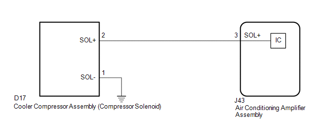
In this circuit, the cooler compressor assembly (compressor solenoid) receives a refrigerant compression demand signal from the air conditioning amplifier assembly.
Based on this signal, the cooler compressor assembly (compressor solenoid) changes the amount of compressor output.
| DTC No. | Detection Item | DTC Detection Condition | Trouble Area | Memory |
|---|---|---|---|---|
| B1451/51 | Compressor Solenoid Circuit | Open or short in compressor solenoid circuit |
| - |
WIRING DIAGRAM
PROCEDURE
| 1. | INSPECT COOLER COMPRESSOR ASSEMBLY (COMPRESSOR SOLENOID) |
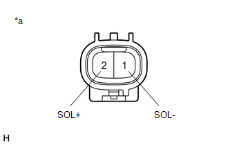
| (a) Disconnect the D17 cooler compressor assembly (compressor solenoid) connector. |
|
(b) Measure the resistance according to the value(s) in the table below.
Standard Resistance:
| Tester Connection | Condition | Specified Condition |
|---|---|---|
| 1 (SOL-) - 2 (SOL+) | 25°C (77°F) | 10.1 to 11.1 Ω |
| NG | .gif) | REPLACE COOLER COMPRESSOR ASSEMBLY (COMPRESSOR SOLENOID) |
.gif)
|
.gif)
| 2. | CHECK HARNESS AND CONNECTOR (COOLER COMPRESSOR ASSEMBLY (COMPRESSOR SOLENOID) - BODY GROUND) |
(a) Measure the resistance according to the value(s) in the table below.
Standard Resistance:
| Tester Connection | Condition | Specified Condition |
|---|---|---|
| D17-1 (SOL-) - Body ground | Always | Below 1 Ω |
| NG | | REPAIR OR REPLACE HARNESS OR CONNECTOR |
|
| 3. | CHECK HARNESS AND CONNECTOR (COOLER COMPRESSOR ASSEMBLY (COMPRESSOR SOLENOID) - AIR CONDITIONING AMPLIFIER ASSEMBLY) |
(a) Disconnect the J43 air conditioning amplifier assembly connector.
(b) Measure the resistance according to the value(s) in the table below.
Standard Resistance:
| Tester Connection | Condition | Specified Condition |
|---|---|---|
| D17-2 (SOL+) - J43-3 (SOL+) | Always | Below 1 Ω |
| D17-2 (SOL+) or J43-3 (SOL+) - Body ground | Always | 10 kΩ or higher |
| Result | Proceed to |
|---|---|
| NG | A |
| OK (When troubleshooting according to the Problem Symptoms Table) | B |
| OK (When troubleshooting according to the DTC) | C |
| A | | REPAIR OR REPLACE HARNESS OR CONNECTOR |
| B | | PROCEED TO NEXT SUSPECTED AREA SHOWN IN PROBLEM SYMPTOMS TABLE |
| C | | REPLACE AIR CONDITIONING AMPLIFIER ASSEMBLY |
 Rear Air Outlet Damper Control Servo Motor Circuit (B1449/49)
DESCRIPTION The No. 2 air conditioning radiator damper servo sub-assembly sends pulse signals to inform the air conditioning amplifier assembly of the damper position. The air conditioning amplifier a ...
 Emission Gas NOx Sensor Circuit (B1461/61)
DESCRIPTION The smog ventilation sensor is installed to the front of the cooler condenser assembly to automatically control the air inlet mode (fresh, recirculation/fresh, and recirculation). This sen ...
Other materials:
Lexus RX (RX 350L, RX450h) 2016-2026 Repair Manual > Brake (front): Front Disc Brake Pad
ReplacementREPLACEMENT CAUTION / NOTICE / HINT NOTICE: After replacing the front disc brake pads, the brake pedal may feel soft due to clearance between the front disc brake pads and front disc. Depress the brake pedal several times until the brake pedal feels firm. HINT:
Use the same procedure f ...
Lexus RX (RX 350L, RX450h) 2016-2026 Repair Manual > Heated Steering Wheel System: Parts Location
PARTS LOCATION ILLUSTRATION *1 SPIRAL CABLE SUB-ASSEMBLY *2 STEERING HEATER SWITCH (INTEGRATION CONTROL AND PANEL ASSEMBLY) *3 STEERING WHEEL ASSEMBLY - STEERING WHEEL HEATER UNIT *4 INSTRUMENT PANEL JUNCTION BLOCK ASSEMBLY - ECU-IG1 NO. 3 FUSE *5 STEERING VIBRATION AND HEA ...
Lexus RX (RX 350L, RX450h) 2016-{YEAR} Owners Manual
- For your information
- Pictorial index
- For safety and security
- Instrument cluster
- Operation of each component
- Driving
- Lexus Display Audio system
- Interior features
- Maintenance and care
- When trouble arises
- Vehicle specifications
- For owners
Lexus RX (RX 350L, RX450h) 2016-{YEAR} Repair Manual

0.0092