Lexus RX (RX 350L, RX450h) 2016-2026 Repair Manual: Reassembly
REASSEMBLY
CAUTION / NOTICE / HINT
NOTICE:
- When using a vise, place aluminum plates between the part and vise.
- When using a vise, do not overtighten it.
PROCEDURE
1. INSTALL CENTER NO. 2 SUPPORT BEARING ASSEMBLY (for Front Side)
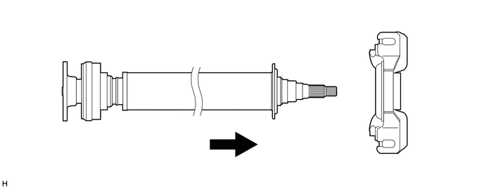
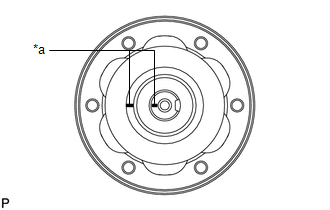
(a) Set the center No. 2 support bearing assembly on the intermediate shaft assembly as shown in the illustration.
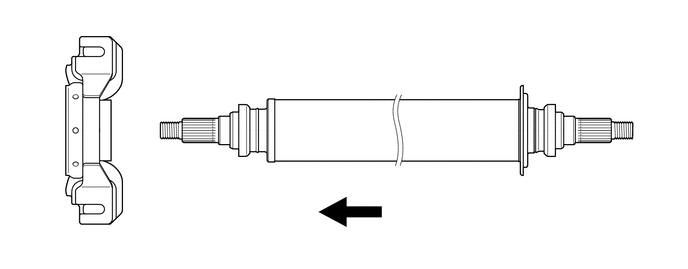
.png) | Front | - | - |
NOTICE:
Make sure to install the center No. 2 support bearing assembly in the correct position.
(b) Install a new washer to the intermediate shaft assembly.
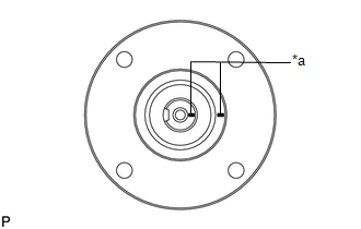
| (c) Align the matchmarks on the intermediate shaft assembly and universal joint flange. |
|
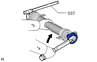
| (d) Using SST to hold the universal joint flange, press the center No. 2 support bearing assembly into position by tightening a new nut and the washer. SST: 09330-00021 Torque: 181.5 N·m {1851 kgf·cm, 134 ft·lbf} |
|
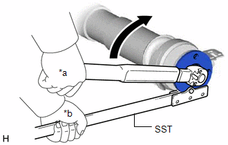
(e) Loosen the nut.
(f) Tighten the nut again.
Torque:
68.7 N·m {701 kgf·cm, 51 ft·lbf}
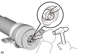
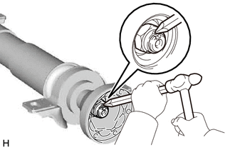
| (g) Using a chisel and a hammer, stake the nut. |
|
2. INSTALL CENTER NO. 2 SUPPORT BEARING ASSEMBLY (for Rear Side)
(a) Set the center No. 2 support bearing assembly on the intermediate shaft assembly as shown in the illustration.
| | Rear | - | - |
NOTICE:
Make sure to install the center No. 2 support bearing assembly in the correct position.
(b) Install a new washer to the intermediate shaft assembly.
| (c) Align the matchmarks on the intermediate shaft assembly and universal joint flange. |
|
| (d) Using SST to hold the universal joint flange, press the center No. 2 support bearing assembly into position by tightening a new nut and the washer. SST: 09330-00021 Torque: 181.5 N·m {1851 kgf·cm, 134 ft·lbf} |
|
(e) Loosen the nut.
(f) Tighten the nut again.
Torque:
68.7 N·m {701 kgf·cm, 51 ft·lbf}
| (g) Using a chisel and a hammer, stake the nut. |
|
3. INSTALL INTERMEDIATE SHAFT ASSEMBLY
| (a) Align the matchmarks on the rear propeller shaft assembly and universal joint flange, and then install the 6 cross groove joint set bolts, 2 universal joint washers. |
|
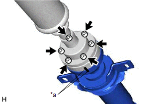
(b) Using a 6 mm hexagon socket wrench, temporarily tighten the 6 cross groove joint set bolts.
4. INSTALL PROPELLER SHAFT ASSEMBLY
| (a) Align the matchmarks on the propeller shaft assembly and universal joint flange. |
|
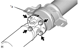
(b) Install the propeller shaft assembly with the 4 bolts, 4 washers and 4 nuts.
Torque:
73.5 N·m {749 kgf·cm, 54 ft·lbf}
HINT:
Install the washers to the same side as the bolts.
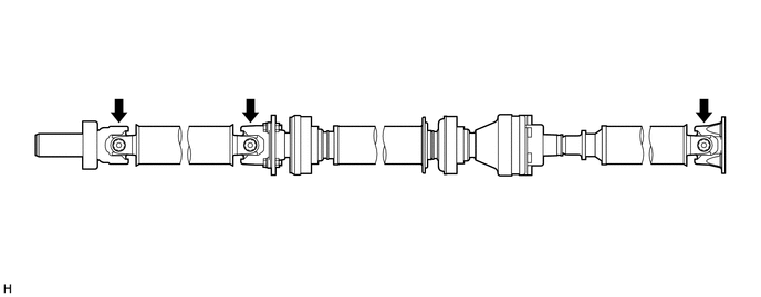
(c) Check that each joint of the propeller with center bearing shaft assembly is facing the direction shown in the illustration.
 Installation
INSTALLATION PROCEDURE 1. TEMPORARILY TIGHTEN PROPELLER WITH CENTER BEARING SHAFT ASSEMBLY (a) Remove SST from the transfer assembly. (b) Insert the propeller with center bearing shaft ...
 Propeller Shaft System
Problem Symptoms TablePROBLEM SYMPTOMS TABLE HINT: Use the table below to help determine the cause of problem symptoms. If multiple suspected areas are listed, the potential causes of the symptoms are ...
Other materials:
Lexus RX (RX 350L, RX450h) 2016-2026 Repair Manual > Audio And Visual System (for 12.3 Inch Display): Speaker Circuit
DESCRIPTION If there is a short in a speaker circuit, the stereo component amplifier assembly detects it and stops output to the speakers. Thus sound cannot be heard from the speakers even if there is no malfunction in the stereo component amplifier assembly or speakers. WIRING DIAGRAM for 9 Speaker ...
Lexus RX (RX 350L, RX450h) 2016-2026 Repair Manual > Sfi System: ECM Power Source Circuit
DESCRIPTION When the engine switch is turned on (IG), the battery voltage is applied to the IGSW terminal of the ECM. The output signal from the MREL terminal of the ECM causes a current to flow to the coil of the semiconductor pwr integration ECU (EFI-MAIN relay), closing the contacts and supplying ...
Lexus RX (RX 350L, RX450h) 2016-{YEAR} Owners Manual
- For your information
- Pictorial index
- For safety and security
- Instrument cluster
- Operation of each component
- Driving
- Lexus Display Audio system
- Interior features
- Maintenance and care
- When trouble arises
- Vehicle specifications
- For owners
Lexus RX (RX 350L, RX450h) 2016-{YEAR} Repair Manual

0.0121