Lexus RX (RX 350L, RX450h) 2016-2026 Repair Manual: ECO Switch Circuit
DESCRIPTION
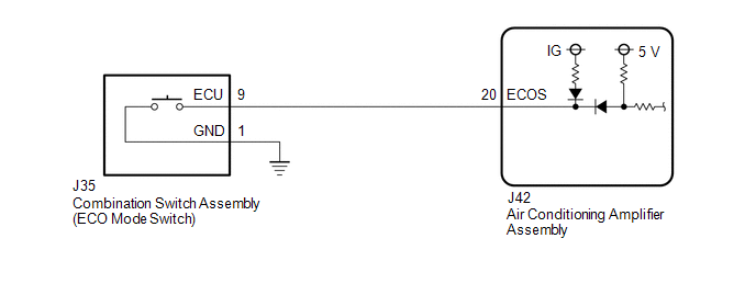
When the combination switch assembly (ECO mode switch) is turned on, the air conditioning amplifier assembly receives a combination switch assembly (ECO mode switch) ON signal and controls the air conditioning to enhance fuel efficiency.
WIRING DIAGRAM
PROCEDURE
| 1. | READ VALUE USING TECHSTREAM |
(a) Connect the Techstream to the DLC3.
(b) Turn the engine switch on (IG).
(c) Turn the Techstream on.
(d) Enter the following menus: Body Electrical / Air Conditioner / Data List.
(e) Read the Data List according to the display on the Techstream.
Body Electrical > Air Conditioner > Data List| Tester Display | Measurement Item | Range | Normal Condition | Diagnostic Note |
|---|---|---|---|---|
| ECO Switch | Combination switch assembly (ECO mode switch) | OFF or ON | ON: Combination switch assembly (ECO mode switch) being turned and held at ECO position OFF: Combination switch assembly (ECO mode switch) not turned | - |
| Tester Display |
|---|
| ECO Switch |
OK:
Combination switch assembly (ECO mode switch) condition displayed on the Techstream changes with the actual switch operation.
| OK | .gif) | PROCEED TO NEXT SUSPECTED AREA SHOWN IN PROBLEM SYMPTOMS TABLE |
|
.gif)
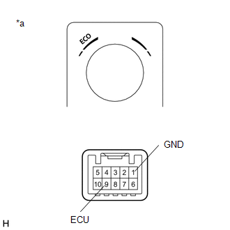
| 2. | INSPECT COMBINATION SWITCH ASSEMBLY (ECO MODE SWITCH) |
(a) Remove the combination switch assembly (ECO mode switch).
Click here .gif)
| (b) Measure the resistance according to the value(s) in the table below. Standard Resistance:
|
|
| NG | | REPLACE COMBINATION SWITCH ASSEMBLY (ECO MODE SWITCH) |
|
| 3. | CHECK HARNESS AND CONNECTOR (COMBINATION SWITCH ASSEMBLY (ECO MODE SWITCH) - AIR CONDITIONING AMPLIFIER ASSEMBLY) |
(a) Disconnect the J42 air conditioning amplifier assembly connector.
(b) Measure the resistance according to the value(s) in the table below.
Standard Resistance:
| Tester Connection | Condition | Specified Condition |
|---|---|---|
| J42-20 (ECOS) - J35-9 (ECU) | Always | Below 1 Ω |
| J42-20 (ECOS) or J35-9 (ECU) - Body ground | Always | 10 kΩ or higher |
| NG | | REPAIR OR REPLACE HARNESS OR CONNECTOR |
|
| 4. | CHECK HARNESS AND CONNECTOR (COMBINATION SWITCH ASSEMBLY (ECO MODE SWITCH) - BODY GROUND) |
(a) Measure the resistance according to the value(s) in the table below.
Standard Resistance:
| Tester Connection | Condition | Specified Condition |
|---|---|---|
| J35-1 (GND) - Body ground | Always | Below 1 Ω |
| OK | | REPLACE AIR CONDITIONING AMPLIFIER ASSEMBLY |
| NG | | REPAIR OR REPLACE HARNESS OR CONNECTOR |
 Back-up Power Source Circuit
DESCRIPTION The back-up power source circuit for the air conditioning amplifier assembly is shown below. Power is supplied even when the engine switch is off. This power is used for diagnostic trouble ...
 IG Power Source Circuit
DESCRIPTION Power source voltage is supplied to the air conditioning amplifier assembly when the engine switch is turned on (IG). This power is used for operating the air conditioning amplifier assemb ...
Other materials:
Lexus RX (RX 350L, RX450h) 2016-2026 Repair Manual > Rear Bumper (w/o Rear No. 2 Seat): Removal
REMOVAL CAUTION / NOTICE / HINT The necessary procedures (adjustment, calibration, initialization, or registration) that must be performed after parts are removed and installed, or replaced during rear bumper assembly removal/installation are shown below. Necessary Procedures After Parts Removed/Ins ...
Lexus RX (RX 350L, RX450h) 2016-2026 Repair Manual > Lighting System (w/ Automatic Headlight Beam Level Control System): Front Fog Light Circuit
DESCRIPTION The main body ECU (multiplex network body ECU) controls the front fog lights. WIRING DIAGRAM CAUTION / NOTICE / HINT NOTICE:
Inspect the fuses for circuits related to this system before performing the following procedure.
Before replacing the main body ECU (multiplex network body E ...
Lexus RX (RX 350L, RX450h) 2016-{YEAR} Owners Manual
- For your information
- Pictorial index
- For safety and security
- Instrument cluster
- Operation of each component
- Driving
- Lexus Display Audio system
- Interior features
- Maintenance and care
- When trouble arises
- Vehicle specifications
- For owners
Lexus RX (RX 350L, RX450h) 2016-{YEAR} Repair Manual

0.0125