Lexus RX (RX 350L, RX450h) 2016-2026 Repair Manual: Removal
REMOVAL
CAUTION / NOTICE / HINT
The necessary procedures (adjustment, calibration, initialization, or registration) that must be performed after parts are removed and installed, or replaced during air conditioning unit removal/installation are shown below.
Necessary Procedure After Parts Removed/Installed/Replaced| Replaced Part or Performed Procedure | Necessary Procedure | Effect/Inoperative Function when Necessary Procedure not Performed | Link |
|---|---|---|---|
|
*1: When performing learning using the Techstream.
Click here | |||
| Disconnect cable from negative battery terminal | Memorize steering angle neutral point | Lane Control System | |
| Pre-collision System | |||
| Intelligent Clearance Sonar System*1 | |||
| Parking Assist Monitor System | | ||
| Panoramic View Monitor System | | ||
| Lighting System (w/ Automatic Headlight Beam Level Control System) | | ||
| Initialize back door lock | Power Door Lock Control System | | |
| Reset back door close position | Power Back Door System (w/ Outside Door Control Switch) | | |
| Removal/installation of the spiral cable with sensor sub-assembly |
| Parking assist monitor system | |
| Steering angle neutral point (Initialize panoramic view monitor system) | Panoramic view monitor system | | |
| Steering angle neutral point (Initialize intelligent clearance sonar system) | Intelligent clearance sonar system | | |
| Initialization servo motor (Air conditioning system) | DTCs are output | |
PROCEDURE
1. PRECAUTION
NOTICE:
- Make sure to select face mode before disconnecting the cable from the negative (-) battery terminal.
- Make sure to perform initialization after replacing the air conditioning radiator damper servo sub-assembly. If initialization is not performed, the air conditioner unit assembly will not perform properly as the air conditioning amplifier assembly will not be able to recognize the position of the air conditioning radiator damper sub-assembly.
2. RECOVER REFRIGERANT FROM REFRIGERATION SYSTEM
Click here .gif)
3. REMOVE WINDSHIELD WIPER MOTOR AND LINK
Click here
4. REMOVE OUTER COWL TOP PANEL SUB-ASSEMBLY
Click here
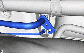
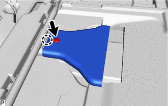
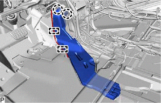
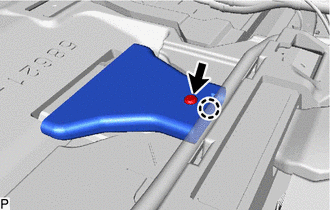
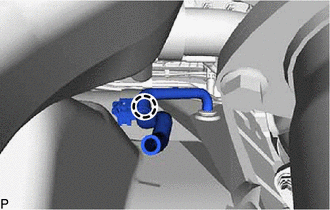
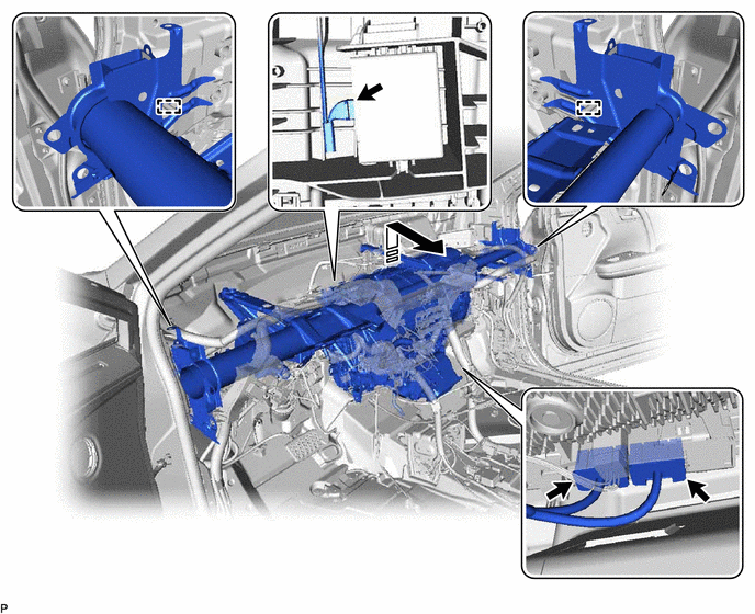
5. DISCONNECT NO. 2 AIR CONDITIONER TUBE AND ACCESSORY ASSEMBLY
| (a) Remove the bolt and rotate the hook connector as shown in the illustration. |
|
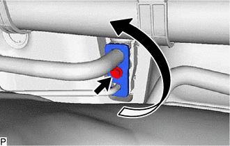
| (b) Disconnect the No. 2 air conditioner tube and accessory assembly. |
|
(c) Remove the 2 O-rings from the No. 2 air conditioner tube and accessory assembly.
NOTICE:
Seal the openings of the disconnected parts using vinyl tape to prevent entry of moisture and foreign matter.
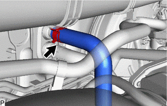
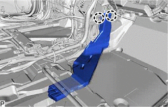
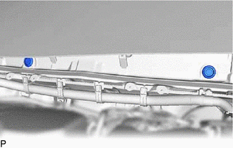
6. DISCONNECT OUTLET HEATER WATER HOSE
| (a) Using pliers, grip the claws of the clip and slide the clip to disconnect the outlet heater water hose. NOTICE:
|
|
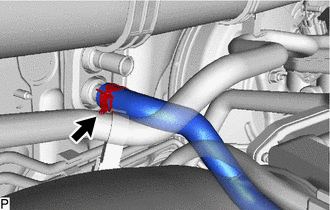
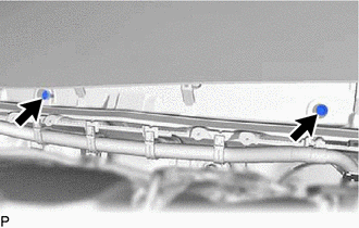
7. DISCONNECT INLET HEATER WATER HOSE
| (a) Using pliers, grip the claws of the clip and slide the clip to disconnect the inlet heater water hose. NOTICE:
|
|
8. REMOVE FRONT SEAT ASSEMBLY LH
Click here
9. REMOVE FRONT SEAT ASSEMBLY RH
HINT:
Use the same procedure as for the LH side.
10. REMOVE INSTRUMENT PANEL SAFETY PAD ASSEMBLY
Click here
11. REMOVE STEERING COLUMN ASSEMBLY
Click here
12. REMOVE ACCELERATOR PEDAL PAD
Click here
13. REMOVE ACCELERATOR PEDAL
Click here
14. REMOVE TRANSMISSION FLOOR SHIFT ASSEMBLY
for U881E Automatic Transmission / Transaxle:
Click here
for U881F Automatic Transmission / Transaxle:
Click here
15. REMOVE DCM (TELEMATICS TRANSCEIVER) WITH BRACKET (w/ Telematics Transceiver)
Click here
16. REMOVE NO. 3 CONSOLE BOX MOUNTING BRACKET
Click here
17. REMOVE SHIFT AND SELECT LEVER SUPPORT
Click here
18. REMOVE NO. 1 CONSOLE BOX DUCT
Click here
19. REMOVE REAR NO. 2 AIR DUCT
| (a) Disengage the 4 guides and turn back the front floor carpet assembly as shown in the illustration. |
|
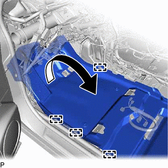
| (b) Remove the clip. |
|
(c) Disengage the claw and remove the rear No. 2 air duct.
20. REMOVE REAR NO. 1 AIR DUCT
| (a) Disengage each clamp. |
|
(b) Disengage the 2 claws and remove the rear No. 1 air duct.
21. REMOVE REAR NO. 4 AIR DUCT
| (a) Disengage the 4 guides and turn back the front floor carpet assembly as shown in the illustration. |
|
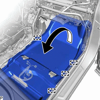
| (b) Remove the clip. |
|
(c) Disengage the claw and remove the rear No. 4 air duct.
22. REMOVE REAR NO. 3 AIR DUCT
| (a) Disengage the 2 claws and remove the rear No. 3 air duct. |
|
23. REMOVE INSTRUMENT PANEL JUNCTION BLOCK ASSEMBLY WITH MAIN BODY ECU
Click here
24. REMOVE PARKING ASSIST ECU (w/ Panoramic View Monitor System)
Click here
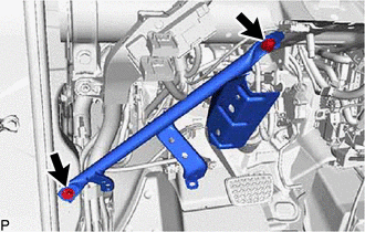
25. REMOVE NO. 1 INSTRUMENT PANEL BRACE SUB-ASSEMBLY
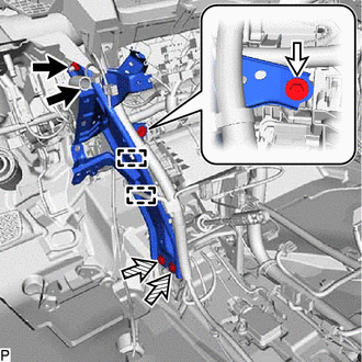
.png) | Nut |
 | Screw |
 | Bolt |
(a) Disengage each clamp.
(b) Remove the 2 nuts, screw, 2 bolts and No. 1 instrument panel brace sub-assembly.
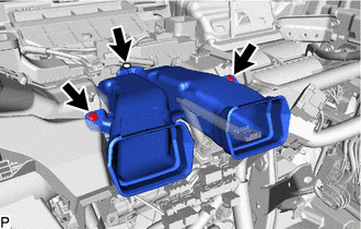
26. REMOVE NO. 2 INSTRUMENT PANEL BRACE SUB-ASSEMBLY
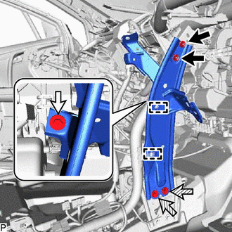
| | Nut |
| | Screw |
| | Bolt |
(a) Disengage each clamp.
(b) Remove the 2 nuts, screw, 2 bolts and No. 2 instrument panel brace sub-assembly.
27. REMOVE INSTRUMENT PANEL REINFORCEMENT SUB-ASSEMBLY
(a) Remove the 2 bolts and instrument panel reinforcement sub-assembly.
28. REMOVE CENTER HEATER TO REGISTER SUB DUCT
(a) Remove the 3 clips and center heater to register sub duct.
29. REMOVE NO. 1 AIR DUCT SUB-ASSEMBLY
| (a) Disengage the clamp. |
|
(b) Disengage the 6 claws to remove the No. 1 air duct sub-assembly.
30. DISCONNECT INSTRUMENT PANEL WIRE
(a) Remove the bolt (A) and disconnect the earth wire.
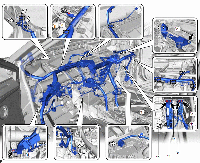
| *1 | ECU Integration Box RH | - | - |
| *a | Earth Wire | *b | Connector Holder |
| *c | Nut (A) | *d | Nut (B) |
| *e | Nut (C) | *f | Nut (D) |
| *g | Bolt (A) | *h | Bolt (B) |
| | Nut | | Connector |
| | Bolt | - | - |
(b) Remove the nut (A).
(c) Remove the nut (B).
(d) Remove the 2 nuts (C) and disconnect the connector holder.
(e) Remove the bolt (B) and 2 nuts (D), and disconnect the ECU integration box RH.
(f) Disconnect each connector.
(g) Disengage each clamp and disconnect the instrument panel wire.
31. REMOVE BRAKE PEDAL RETURN SPRING
Click here
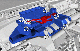
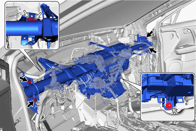
32. REMOVE INSTRUMENT PANEL REINFORCEMENT ASSEMBLY WITH AIR CONDITIONER UNIT ASSEMBLY
NOTICE:
- Be sure to support the air conditioner unit assembly when removing it. Failure to do so may cause the bracket of the air conditioner unit assembly to break.
- When disassembling the air conditioner unit assembly, eliminate static electricity by touching the vehicle body to prevent the components from being damaged.
| (a) Remove the 2 hole plugs. |
|
| (b) Remove the 2 bolts. |
|
| (c) Disengage the claw and disconnect the drain cooler hose from the piping clamp. |
|
(d) Remove the 4 bolts (A).
| | Bolt (A) | | Bolt (B) |
| | Nut | - | - |
(e) Remove the 2 bolts (B) and disconnect the brake pedal support assembly.
(f) Remove the nut.
(g) Disconnect each connector.
.png) | Remove in this Direction | - | - |
(h) Disengage the 2 guides and remove the instrument panel reinforcement assembly with air conditioner unit assembly as shown in the illustration.
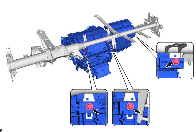
33. REMOVE AIR CONDITIONER UNIT ASSEMBLY
(a) Remove the 3 bolts and air conditioner unit assembly from the instrument panel reinforcement assembly.
 Components
COMPONENTS ILLUSTRATION *1 OUTER COWL TOP PANEL SUB-ASSEMBLY - - N*m (kgf*cm, ft.*lbf): Specified torque - - ILLUSTRATION *1 INLET HEATER WATER HOSE *2 NO. 2 AIR COND ...
 Disassembly
DISASSEMBLY PROCEDURE 1. PRECAUTION NOTICE: Make sure to perform initialization after replacing the air conditioning radiator damper servo sub-assembly. If initialization is not performed, the air con ...
Other materials:
Lexus RX (RX 350L, RX450h) 2016-2026 Repair Manual > Lexus Enform System: Confirm Vehicle Headunit Functionality
PROCEDURE 1. CHECK CUSTOMER'S CELLULAR PHONE COMPATIBILITY (a) Check if the cellular phone is compatible (Refer to http://www.lexus.com/MobileLink/). Result Proceed to Cellular phone is compatible. A Cellular phone is not compatible. B HINT: It is important to check the ...
Lexus RX (RX 350L, RX450h) 2016-2026 Repair Manual > Door Lock: Wireless Door Lock Buzzer
ComponentsCOMPONENTS ILLUSTRATION *A for TMMC Made - - *1 FRONT FENDER SPLASH SHIELD SUB-ASSEMBLY LH *2 FRONT WHEEL OPENING EXTENSION PAD LH *3 WIRELESS DOOR LOCK BUZZER - - InstallationINSTALLATION PROCEDURE 1. INSTALL WIRELESS DOOR LOCK BUZZER (a) Engage the clamp ...
Lexus RX (RX 350L, RX450h) 2016-{YEAR} Owners Manual
- For your information
- Pictorial index
- For safety and security
- Instrument cluster
- Operation of each component
- Driving
- Lexus Display Audio system
- Interior features
- Maintenance and care
- When trouble arises
- Vehicle specifications
- For owners
Lexus RX (RX 350L, RX450h) 2016-{YEAR} Repair Manual

0.0131