Lexus RX (RX 350L, RX450h) 2016-2026 Repair Manual: Disassembly
DISASSEMBLY
PROCEDURE
1. PRECAUTION
NOTICE:
Make sure to perform initialization after replacing the air conditioning radiator damper servo sub-assembly. If initialization is not performed, the air conditioner unit assembly will not perform properly as the air conditioning amplifier assembly will not be able to recognize the position of the air conditioning radiator damper sub-assembly.
2. REMOVE NO. 5 AIR DUCT SUB-ASSEMBLY
| (a) Remove the screw. |
|
(b) Disengage the 3 claws to remove the No. 5 air duct sub-assembly.
3. REMOVE ASPIRATOR
| (a) Disengage the 2 claws to remove the aspirator. |
|
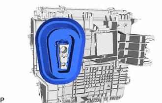
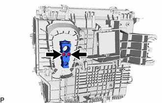
4. REMOVE ID CODE BOX (IMMOBILISER CODE ECU)
Click here .gif)
5. REMOVE BLOWER ASSEMBLY
Click here
6. REMOVE NO. 2 HEATER COVER
| (a) Remove the screw. |
|
(b) Disengage the claw and guide to remove the No. 2 heater cover.
7. REMOVE HEATER COVER (w/o PTC Heater)
(a) Disengage the guide and remove the heater cover as shown in the illustration.
.png) | Remove in this Direction |
8. REMOVE QUICK HEATER ASSEMBLY (w/ PTC Heater)
(a) Disengage the guide and remove the quick heater assembly as shown in the illustration.
| | Remove in this Direction |
9. REMOVE AIR CONDITIONING HARNESS ASSEMBLY
(a) Disconnect each connector.
(b) Disengage each clamp to remove the air conditioning harness assembly.
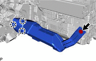
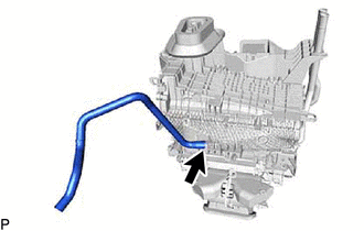
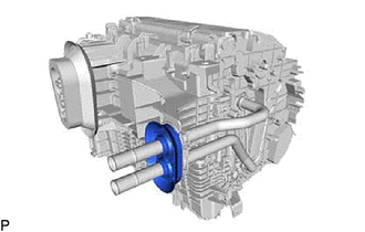
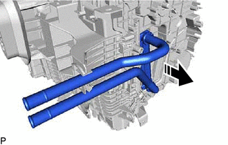
10. REMOVE DRAIN COOLER HOSE
| (a) Remove the drain cooler hose. |
|
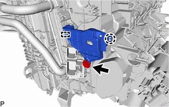
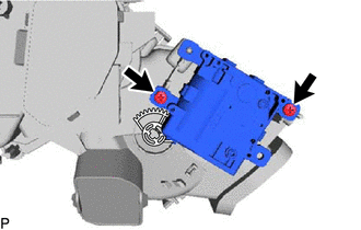
11. REMOVE AIR CONDITIONING AMPLIFIER ASSEMBLY
Click here
12. REMOVE NO. 1 AIR CONDITIONING RADIATOR DAMPER SERVO SUB-ASSEMBLY
| (a) Remove the 3 screws and No. 1 air conditioning radiator damper servo sub-assembly. |
|
13. REMOVE NO. 3 AIR CONDITIONING RADIATOR DAMPER SERVO SUB-ASSEMBLY
| (a) Remove the 2 screws and No. 3 air conditioning radiator damper servo sub-assembly. |
|
14. REMOVE NO. 2 AIR CONDITIONING RADIATOR DAMPER SERVO SUB-ASSEMBLY
| (a) Remove the 2 screws and No. 2 air conditioning radiator damper servo sub-assembly. |
|
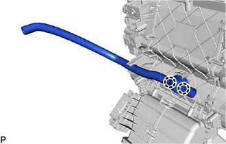
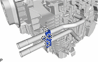
15. REMOVE HEATER GROMMET
| (a) Remove the heater grommet. |
|
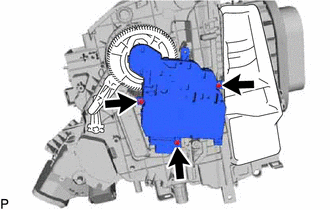
16. REMOVE HEATER RADIATOR UNIT SUB-ASSEMBLY
| (a) Disengage the 4 claws to remove the heater clamp. |
|
| | Remove in this Direction |
(b) Remove the heater radiator unit sub-assembly as shown in the illustration.
NOTICE:
Prepare a drain pan or cloth in case the coolant leaks.
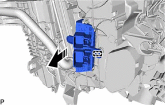
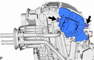
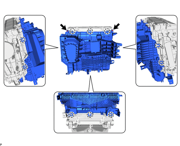
17. REMOVE COOLING UNIT PARTS
| (a) Remove the cooling unit parts. |
|
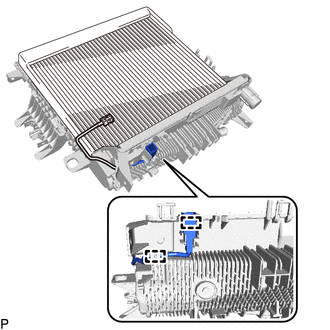
18. REMOVE COOLER EXPANSION VALVE
| (a) Using a 4 mm hexagon socket wrench, remove the 2 hexagon bolts and cooler expansion valve. |
|
(b) Remove the 2 O-rings from the No. 1 cooler evaporator sub-assembly.
19. REMOVE NO. 1 COOLER EVAPORATOR SUB-ASSEMBLY
(a) Remove the 2 screws.
(b) Disengage the 10 claws to remove the upper heater case with No. 1 cooler evaporator sub-assembly from the lower heater case.
| (c) Disengage the 2 clamps. |
|
(d) Remove the No. 1 cooler evaporator sub-assembly with No. 1 cooler thermistor from the upper heater case.
NOTICE:
When the No. 1 cooler evaporator sub-assembly is removed, make sure to install a new one. The No. 1 cooler evaporator sub-assembly cannot be reused.
20. REMOVE NO. 1 COOLER THERMISTOR
Click here
 Removal
REMOVAL CAUTION / NOTICE / HINT The necessary procedures (adjustment, calibration, initialization, or registration) that must be performed after parts are removed and installed, or replaced during air ...
 Installation
INSTALLATION PROCEDURE 1. TEMPORARILY INSTALL AIR CONDITIONER UNIT ASSEMBLY (a) Temporarily install the air conditioner unit assembly to the instrument panel reinforcement assembly with the 3 bolts. 2 ...
Other materials:
Lexus RX (RX 350L, RX450h) 2016-2026 Repair Manual > Safety Connect System: Telephone Sub Antenna Circuit Short to Ground (B153711,B153713)
DESCRIPTION These DTCs are stored when a malfunction occurs in the telephone and GPS antenna (for Front Side). DTC No. Detection Item DTC Detection Condition Trouble Area B153711 Telephone Sub Antenna Circuit Short to Ground Telephone antenna (sub) impedance (Ω) is lower than the m ...
Lexus RX (RX 350L, RX450h) 2016-2026 Repair Manual > Fuel Pump (for Tmc Made): Components
COMPONENTS ILLUSTRATION *A w/ Rear No. 2 Seat - - *1 REAR DOOR INSIDE SCUFF PLATE LH *2 REAR DOOR SCUFF PLATE LH *3 FRONT DECK SIDE TRIM COVER LH *4 REAR SEAT SIDE GARNISH LH ILLUSTRATION *A w/ Rear No. 2 Seat - - *1 REAR DOOR INSIDE SCUFF PLATE RH ...
Lexus RX (RX 350L, RX450h) 2016-{YEAR} Owners Manual
- For your information
- Pictorial index
- For safety and security
- Instrument cluster
- Operation of each component
- Driving
- Lexus Display Audio system
- Interior features
- Maintenance and care
- When trouble arises
- Vehicle specifications
- For owners
Lexus RX (RX 350L, RX450h) 2016-{YEAR} Repair Manual

0.0109