Lexus RX (RX 350L, RX450h) 2016-2026 Repair Manual: Removal
REMOVAL
PROCEDURE
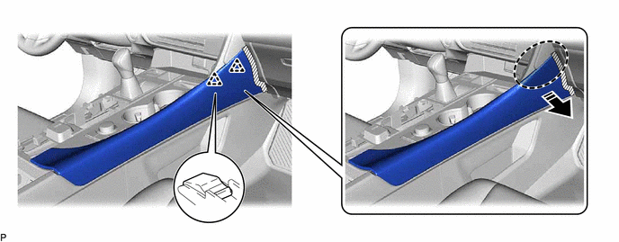
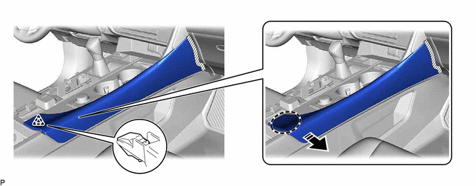
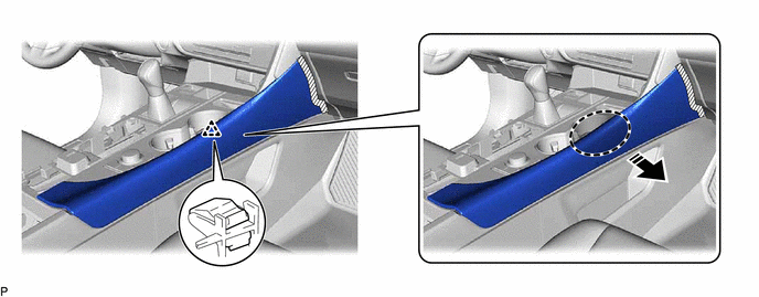
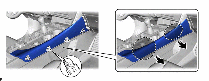
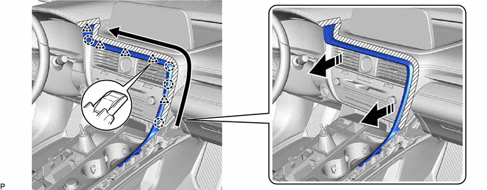
1. REMOVE REAR CONSOLE UPPER PANEL
(a) Disengage the 3 clips and 2 claws in the direction indicated by the arrow (1).
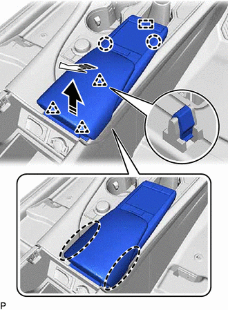
 | Place Hand Here |
.png) | Remove in this Direction (1) |
.png) | Remove in this Direction (2) |
(b) Pull the rear console upper panel in the direction indicated by the arrow (2) to disengage the guide.
(c) Disconnect the connector to remove the rear console upper panel.
2. REMOVE LOWER NO. 2 INSTRUMENT PANEL FINISH PANEL
(a) Apply protective tape to the area shown in the illustration.
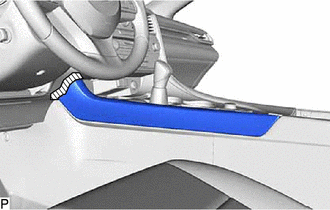
.png) | Protective Tape |
(b) Disengage the 7 clips to remove the lower No. 2 instrument panel finish panel as shown in the illustration.
| | Place Hand Here | | Remove in this Direction |
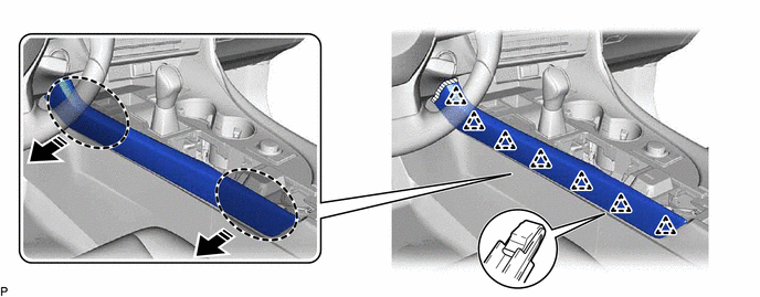
3. REMOVE LOWER NO. 1 INSTRUMENT PANEL FINISH PANEL
NOTICE:
Make sure to perform this procedure carefully, otherwise the lower No. 1 instrument panel finish panel may be damaged.
(a) Apply protective tape to the area shown in the illustration.
| | Protective Tape |
(b) Disengage the 2 clips as shown in the illustration.
| | Place Hand Here | | Remove in this Direction |
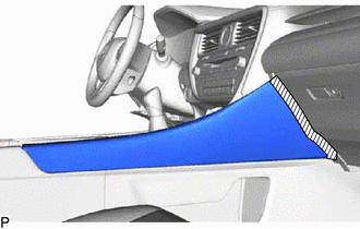
(c) Disengage the clip as shown in the illustration.
| | Place Hand Here | | Remove in this Direction |
(d) Disengage the clip as shown in the illustration.
| | Place Hand Here | | Remove in this Direction |
(e) Disengage the 4 clips to remove the lower No. 1 instrument panel finish panel as shown in the illustration.
| | Place Hand Here | | Remove in this Direction |
4. REMOVE SHIFT LEVER KNOB SUB-ASSEMBLY
(a) Disengage the claw and disconnect the shift hole cover sub-assembly as shown in the illustration.
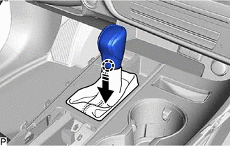
| | Remove in this Direction |
(b) Turn the shift lever knob sub-assembly counterclockwise and remove it.
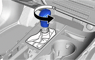
| | Remove in this Direction |
5. REMOVE INSTRUMENT CLUSTER FINISH PANEL ORNAMENT
(a) Apply protective tape to the areas shown in the illustration.
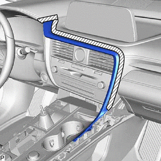
| | Protective Tape |
(b) Disengage the 2 clips as shown in the illustration.
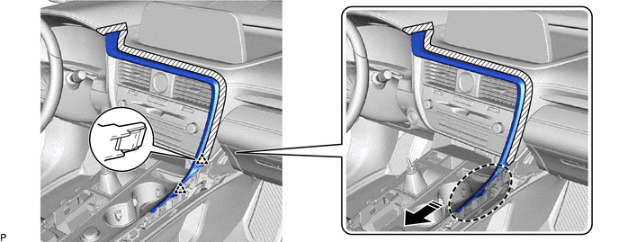
| | Place Hand Here | | Remove in this Direction |
(c) Disengage the 4 claws and 5 clips to remove the instrument cluster finish panel ornament as shown in the illustration.
| | Remove in this Direction | .png) | Order of Removal |
6. REMOVE CONSOLE PANEL SUB-ASSEMBLY
| (a) Disengage the clamp. |
|
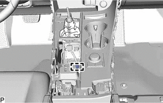
(b) Move the shift lever to N.
| (c) Remove the 2 screws. |
|
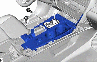
(d) Disengage the 4 clips and 5 guides as shown in the illustration.
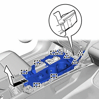
| | Remove in this Direction |
(e) Disconnect each connector to remove the console panel sub-assembly.
7. REMOVE INSTRUMENT PANEL CUP HOLDER ASSEMBLY
| (a) Remove the 6 screws and instrument panel cup holder assembly. |
|
8. REMOVE CONSOLE REAR END PANEL SUB-ASSEMBLY
(a) Using a moulding remover B, disengage the clip as shown in the illustration.
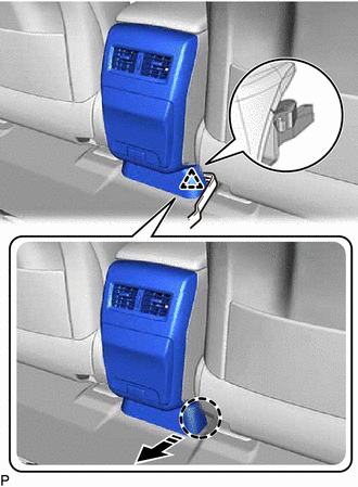
| | Insert Moulding Remover B Here |
| | Remove in this Direction |
(b) Using a moulding remover B, disengage the clip as shown in the illustration.
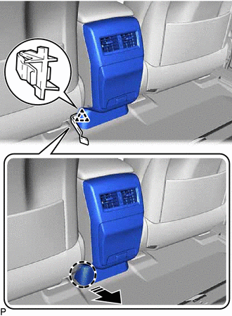
| | Insert Moulding Remover B Here |
| | Remove in this Direction |
(c) Disengage the 4 clips and 4 claws as shown in the illustration.
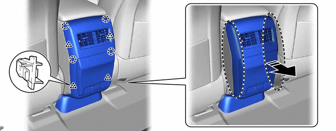
| | Place Hand Here | | Remove in this Direction |
(d) Disconnect each connector to remove the console rear end panel sub-assembly.
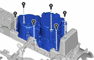
9. REMOVE CONSOLE BOX ASSEMBLY
| (a) Disengage the clamp. |
|
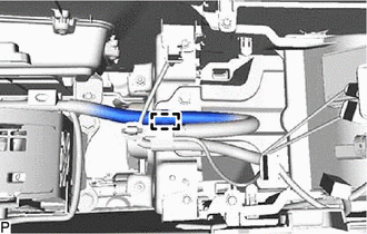
| (b) Disengage the clamp. |
|
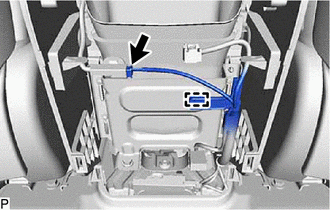
(c) Disconnect the connector.
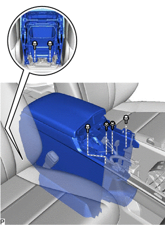
| (d) Remove the 4 bolts and 2 screws. |
|
(e) Disconnect each connector.
(f) Pull the console box assembly as shown in the illustration to disengage the 6 guides and remove the console box assembly.
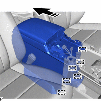
| | Remove in this Direction |
 Components
COMPONENTS ILLUSTRATION *1 CONSOLE BOX ASSEMBLY *2 CONSOLE PANEL SUB-ASSEMBLY *3 CONSOLE REAR END PANEL SUB-ASSEMBLY *4 INSTRUMENT CLUSTER FINISH PANEL ORNAMENT *5 INSTRUMENT ...
 Disassembly
DISASSEMBLY PROCEDURE 1. REMOVE CONSOLE COIN BOX (w/ Console Coin Box) (a) Remove the console coin box. 2. REMOVE REAR CONSOLE BOX GARNISH (a) Disengage the 3 clips as shown in the illu ...
Other materials:
Lexus RX (RX 350L, RX450h) 2016-2026 Repair Manual > Automatic Transaxle System: Parts Location
PARTS LOCATION ILLUSTRATION *1 ECM *2 ENGINE ROOM RELAY BLOCK AND JUNCTION BLOCK ASSEMBLY - EFI-MAIN FUSE - ETCS FUSE - ST RELAY ILLUSTRATION *1 SHIFT SOLENOID VALVE SL1 *2 SHIFT SOLENOID VALVE SL2 *3 SHIFT SOLENOID VALVE SL3 *4 SHIFT SOLENOID VALVE SL4 *5 SHIF ...
Lexus RX (RX 350L, RX450h) 2016-2026 Repair Manual > Theft Deterrent System: Precaution
PRECAUTION PRECAUTION FOR DISCONNECTING CABLE FROM NEGATIVE BATTERY TERMINAL NOTICE: When disconnecting the cable from the negative (-) battery terminal, initialize the following systems after the cable is reconnected. System Name See Procedure Lane Control System Pre-collision Sys ...
Lexus RX (RX 350L, RX450h) 2016-{YEAR} Owners Manual
- For your information
- Pictorial index
- For safety and security
- Instrument cluster
- Operation of each component
- Driving
- Lexus Display Audio system
- Interior features
- Maintenance and care
- When trouble arises
- Vehicle specifications
- For owners
Lexus RX (RX 350L, RX450h) 2016-{YEAR} Repair Manual

0.0105