Lexus RX (RX 350L, RX450h) 2016-2026 Repair Manual: Disassembly
DISASSEMBLY
PROCEDURE
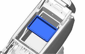
1. REMOVE CONSOLE COIN BOX (w/ Console Coin Box)
| (a) Remove the console coin box. |
|
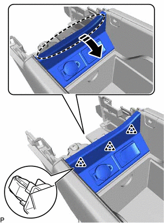
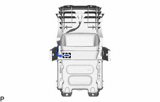
2. REMOVE REAR CONSOLE BOX GARNISH
(a) Disengage the 3 clips as shown in the illustration.
.png) | Place Hand Here |
.png) | Remove in this Direction |
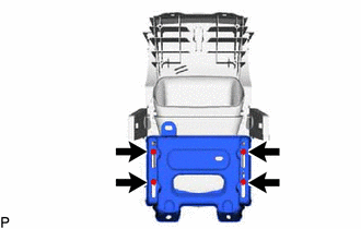
(b) Disengage the 3 guides to remove the rear console box garnish as shown in the illustration.
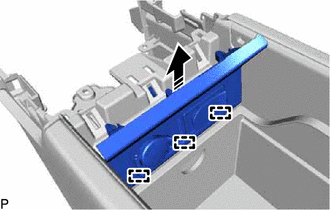
| | Remove in this Direction |
3. REMOVE NO. 2 POWER OUTLET SOCKET ASSEMBLY
Click here .gif)
4. REMOVE NO. 2 POWER OUTLET SOCKET COVER
Click here
5. REMOVE NO. 1 STEREO JACK ADAPTER ASSEMBLY
Click here
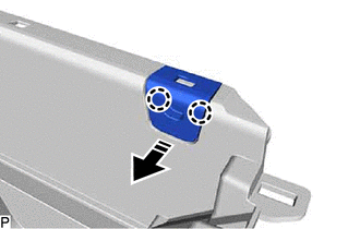
6. REMOVE LOWER CONSOLE BOX POCKET (for TMMC Made)
(a) Remove the lower console box pocket as shown in the illustration.
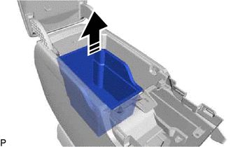
| | Remove in this Direction |
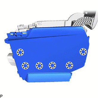
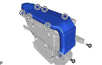
7. REMOVE NO. 1 BOX SIDE PANEL
| (a) Disengage the 6 claws. |
|
(b) Using a moulding remover A, disengage the 3 claws to remove the No. 1 box side panel as shown in the illustration.
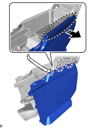
| | Insert Moulding Remover A Here |
| | Remove in this Direction |
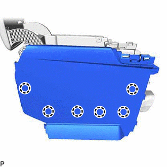
8. REMOVE NO. 2 BOX SIDE PANEL
| (a) Disengage the 6 claws. |
|
(b) Using a moulding remover A, disengage the 3 claws to remove the No. 2 box side panel as shown in the illustration.
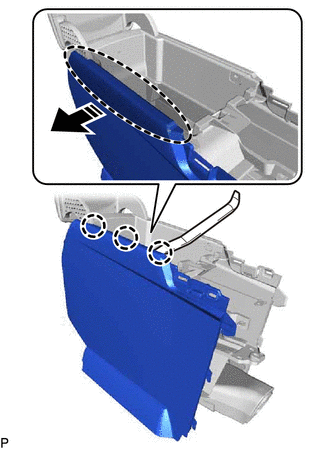
| | Insert Moulding Remover A Here |
| | Remove in this Direction |
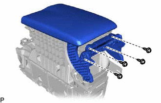
9. REMOVE REAR CONSOLE ARMREST ASSEMBLY
| (a) Remove the 4 screws and rear console armrest assembly. |
|
10. REMOVE CONSOLE COMPARTMENT DOOR LOCK SUB-ASSEMBLY
(a) Using a moulding remover B, disengage the 10 claws to remove the console compartment door lock sub-assembly as shown in the illustration.
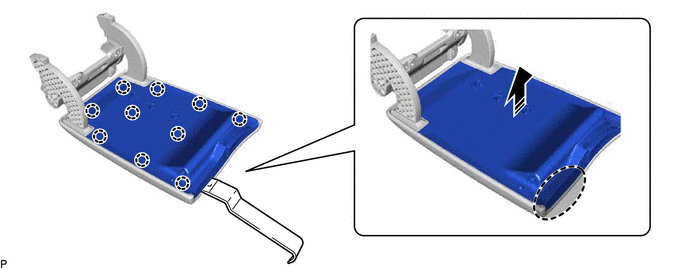
| | Insert Moulding Remover B Here | | Remove in this Direction |
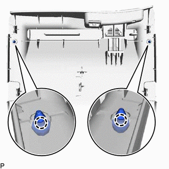
11. REMOVE CONSOLE COMPARTMENT DOOR CUSHION
| (a) Disengage the 2 claws to remove the 2 console compartment door cushions. |
|
12. REMOVE GLOVE COMPARTMENT BOX BAND
(a) Using pliers, remove the 2 glove compartment box bands as indicated by the arrows, in the order shown in the illustration.
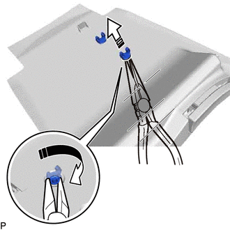
| | Remove in this Direction (1) |
.png) | Remove in this Direction (2) |
13. REMOVE NO. 2 CONSOLE BOX DUCT
| (a) Disengage the clamp. |
|
| (b) Remove the 4 screws and No. 9 console box retainer. |
|
| (c) Remove the 2 screws. |
|
(d) Disengage the 6 claws to remove the No. 2 console box duct.
14. REMOVE NO. 1 BOX PLATE UPPER
(a) Disengage the 2 claws to remove the No. 1 box plate upper as shown in the illustration.
| | Remove in this Direction |
HINT:
Use the same procedure for the RH side and LH side.
15. REMOVE NO. 1 INTERIOR ILLUMINATION LIGHT ASSEMBLY (for Front Side)
Click here
16. REMOVE NO. 1 INTERIOR ILLUMINATION LIGHT ASSEMBLY (for Rear Side)
Click here
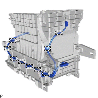
17. REMOVE REAR CONSOLE BOX WIRE
| (a) Disengage the 9 clamps to remove the rear console box wire. |
|
 Removal
REMOVAL PROCEDURE 1. REMOVE REAR CONSOLE UPPER PANEL (a) Disengage the 3 clips and 2 claws in the direction indicated by the arrow (1). Place Hand Here Remove in this Direction (1) ...
 Installation
INSTALLATION PROCEDURE 1. INSTALL CONSOLE BOX ASSEMBLY (a) Engage the 6 guides as shown in the illustration. Install in this Direction (b) Connect each connector. (c) Install the console box ...
Other materials:
Lexus RX (RX 350L, RX450h) 2016-2026 Repair Manual > Airbag System: Short in Rear P/T Squib (LH) Circuit (B1925-B1928)
DESCRIPTION The rear pretensioner squib LH circuit consists of the airbag sensor assembly and rear No. 1 seat outer belt assembly LH. The airbag sensor assembly uses this circuit to deploy the pretensioner when deployment conditions are met. These DTCs are stored when a malfunction is detected in th ...
Lexus RX (RX 350L, RX450h) 2016-2026 Repair Manual > Power Steering System: Torque Sensor1 (C1511-C1514,C1517)
DESCRIPTION The torque sensor converts the rotational torque received from the steering wheel into electric signals and sends them to the power steering ECU assembly. DTC No. Detection Item DTC Detection Condition Trouble Area Warning Indicate Return-to-normal Condition Note C1511 ...
Lexus RX (RX 350L, RX450h) 2016-{YEAR} Owners Manual
- For your information
- Pictorial index
- For safety and security
- Instrument cluster
- Operation of each component
- Driving
- Lexus Display Audio system
- Interior features
- Maintenance and care
- When trouble arises
- Vehicle specifications
- For owners
Lexus RX (RX 350L, RX450h) 2016-{YEAR} Repair Manual

0.012