Lexus RX (RX 350L, RX450h) 2016-2026 Repair Manual: Entire Combination Meter does not Operate
DESCRIPTION
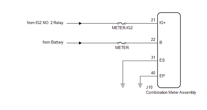
This circuit is the power source circuit for the combination meter assembly. This circuit provides two types of power sources; one is a constant power source, and the other is an IG power source.
WIRING DIAGRAM
CAUTION / NOTICE / HINT
NOTICE:
- When replacing the combination meter assembly, always replace it with a new one. If a combination meter assembly which was installed to another vehicle is used, the information stored in it will not match the information from the vehicle and a DTC may be stored.
- Inspect the fuses of circuits related to this system before performing the following procedure.
PROCEDURE
| 1. | CHECK HARNESS AND CONNECTOR (POWER SOURCE CIRCUIT) |
(a) Disconnect the J10 combination meter assembly connector.
(b) Measure the resistance according to the value(s) in the table below.
Standard Resistance:
| Tester Connection | Condition | Specified Condition |
|---|---|---|
| J10-31 (ES) - Body ground | Always | Below 1 Ω |
| J10-40 (EP) - Body ground | Always | Below 1 Ω |
(c) Measure the voltage according to the value(s) in the table below.
Standard Voltage:
| Tester Connection | Condition | Specified Condition |
|---|---|---|
| J10-21 (IG+) - Body ground | Engine switch off | Below 1 V |
| Engine switch on (IG) | 11 to 14 V | |
| J10-22 (B) - Body ground | Always | 11 to 14 V |
| OK | .gif) | REPLACE COMBINATION METER ASSEMBLY |
.gif)
| NG | | REPAIR OR REPLACE HARNESS OR CONNECTOR |
 Short in Turn Signal / Hazard Flasher Circuit (B1508)
DESCRIPTION This DTC is stored when the combination meter assembly detects a short in a turn signal light circuit. HINT: If there is a short in a turn signal light circuit, all of the turn signal ligh ...
 Lost Communication with ECM / PCM "A" (U0100,U0129,U0131,U0140,U0151,U0163,U0182,U023A)
DESCRIPTION The combination meter assembly communicates with the ECM, brake actuator assembly (skid control ECU), power steering ECU assembly, main body ECU (multiplex network body ECU), airbag sensor ...
Other materials:
Lexus RX (RX 350L, RX450h) 2016-2026 Repair Manual > Lane Control System: Steering Vibrator Component Internal Failure (C1A7496)
DESCRIPTION If the forward recognition camera receives a steering vibration ECU malfunction signal, DTC C1A7496 is stored. DTC No. Detection Item DTC Detection Condition Trouble Area C1A7496 Steering Vibrator Component Internal Failure While the lane control system is on, a malfunct ...
Lexus RX (RX 350L, RX450h) 2016-2026 Owners Manual > Using the other interior
features: LEXUS Enform Safety
Connect
Safety Connect is a subscription-based telematics service that uses
Global
Positioning System (GPS) data and embedded cellular technology to provide
safety and security features to subscribers. Safety Connect is supported by
Lexus' designated response center, which operates 24 hours per day, 7 ...
Lexus RX (RX 350L, RX450h) 2016-{YEAR} Owners Manual
- For your information
- Pictorial index
- For safety and security
- Instrument cluster
- Operation of each component
- Driving
- Lexus Display Audio system
- Interior features
- Maintenance and care
- When trouble arises
- Vehicle specifications
- For owners
Lexus RX (RX 350L, RX450h) 2016-{YEAR} Repair Manual

0.016