Lexus RX (RX 350L, RX450h) 2016-2026 Repair Manual: Speed Signal Circuit
DESCRIPTION
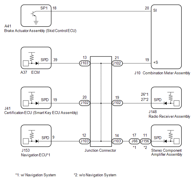
The combination meter assembly receives the vehicle speed signal from this circuit. The wheel speed sensors produce an output that varies according to the vehicle speed. The wheel speed sensor output is received by the brake actuator assembly (skid control ECU) which uses this information to create the vehicle speed signal*a. The vehicle speed signal consists of pulses sent to the combination meter assembly from the brake actuator assembly (skid control ECU). To create this signal, 12 V is output from IG2 which is behind a resistor in the combination meter assembly. This voltage is sent to the brake actuator assembly (skid control ECU). The pulse signal is created by switching the transistor in the brake actuator assembly (skid control ECU) on and off, making the voltage on the wire drop to 0 V. A similar system is used for the output of this signal from the combination meter assembly via terminal +S. A voltage of 12 V or 5 V is applied to terminal +S from each ECU or relay that is connected to this terminal. The transistor in the combination meter assembly is controlled by the signal from the brake actuator assembly (skid control ECU). When this transistor is turned on, this transistor makes the voltage supplied by the various ECUs (via their respective internal resistors) drop to 0 V. Each ECU connected to terminal +S of the combination meter assembly controls its respective system based on this pulse signal.
- *a: This vehicle speed signal is created by the brake actuator assembly (skid control ECU). There is no actual component that is referred to as the vehicle speed sensor. In addition, for some systems, vehicle speed information may be received via CAN communication.
HINT:
This circuit is used for the systems connected to terminal +S. This signal is not used for combination meter assembly operation. Combination meter assembly components such as the speedometer operate using data received via CAN communication.
WIRING DIAGRAM
CAUTION / NOTICE / HINT
NOTICE:
- When replacing the combination meter assembly, always replace it with a new one. If a combination meter assembly which was installed to another vehicle is used, the information stored in it will not match the information from the vehicle and a DTC may be stored.
-
Before replacing the ECM or certification ECU (smart key ECU assembly), refer to Registration.
Click here
.gif)
PROCEDURE
| 1. | INSPECT ECU TERMINAL VOLTAGE (INPUT VOLTAGE) |
| (a) Disconnect the J10 combination meter assembly connector. |
|
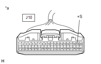
(b) Measure the voltage according to the value(s) in the table below.
Standard Voltage:
| Tester Connection | Condition | Specified Condition |
|---|---|---|
| J10-19 (+S) - Body ground | Engine switch on (IG) | 4.5 to 14 V |
HINT:
If any of the ECUs specified in the wiring diagram supplies power to the combination meter assembly, the combination meter assembly will output a waveform.
| NG | .gif) | GO TO STEP 5 |
|
.gif)
| 2. | INSPECT COMBINATION METER ASSEMBLY (OUTPUT VOLTAGE) |
(a) Reconnect the J10 combination meter assembly connector.
| (b) Disconnect the A41 brake actuator assembly (skid control ECU) connector. |
|
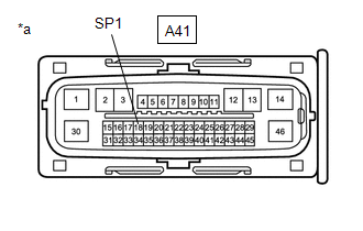
(c) Measure the voltage according to the value(s) in the table below.
Standard Voltage:
| Tester Connection | Condition | Specified Condition |
|---|---|---|
| A41-18 (SP1) - Body ground | Engine switch on (IG) | 11 to 14 V |
| NG | | GO TO STEP 4 |
|
| 3. | INSPECT BRAKE ACTUATOR ASSEMBLY (SKID CONTROL ECU) (INPUT WAVEFORM) |
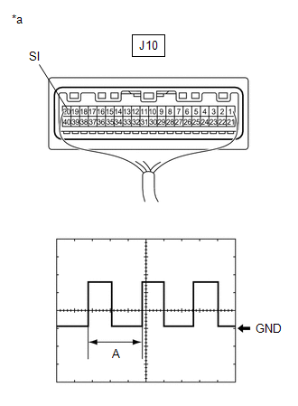
| (a) Check the input waveform. (1) Reconnect the A41 brake actuator assembly (skid control ECU) connector. (2) Remove the combination meter assembly with the connector(s) still connected. (3) Connect an oscilloscope to terminal J10-20 (SI) and body ground. (4) Turn the engine switch on (IG). (5) Turn a wheel slowly. (6) Check the signal waveform according to the condition(s) in the table below.
OK: The waveform is similar to that shown in the illustration. HINT: When the system is functioning normally, one wheel revolution generates 4 pulses. As the vehicle speed increases, the width indicated by (A) in the illustration narrows. |
|
| OK | | REPLACE COMBINATION METER ASSEMBLY |
| NG | | REPLACE BRAKE ACTUATOR ASSEMBLY (SKID CONTROL ECU) |
| 4. | CHECK HARNESS AND CONNECTOR (COMBINATION METER ASSEMBLY - BRAKE ACTUATOR ASSEMBLY (SKID CONTROL ECU)) |
(a) Disconnect the J10 combination meter assembly connector.
(b) Measure the resistance according to the value(s) in the table below.
Standard Resistance:
| Tester Connection | Condition | Specified Condition |
|---|---|---|
| J10-20 (SI) - A41-18 (SP1) | Always | Below 1 Ω |
| J10-20 (SI) or A41-18 (SP1) - Body ground | Always | 10 kΩ or higher |
| OK | | REPLACE COMBINATION METER ASSEMBLY |
| NG | | REPAIR OR REPLACE HARNESS OR CONNECTOR |
| 5. | CHECK HARNESS AND CONNECTOR (COMBINATION METER ASSEMBLY - JUNCTION CONNECTOR) |
(a) Disconnect the J102 junction connector.
(b) Measure the resistance according to the value(s) in the table below.
Standard Resistance:
| Tester Connection | Condition | Specified Condition |
|---|---|---|
| J10-19 (+S) - J102-21 | Always | Below 1 Ω |
| J10-19 (+S) or J102-21 - Body ground | Always | 10 kΩ or higher |
| NG | | REPAIR OR REPLACE HARNESS OR CONNECTOR |
|
| 6. | CHECK HARNESS AND CONNECTOR (JUNCTION CONNECTOR) |
(a) Check for a short in the wire harness and connectors connected to the junction connector shown in the wiring diagram.
HINT:
If voltage is not present, it is possible that an ECU or circuit has a malfunction. The malfunctioning ECU or circuit will be diagnosed in the following steps.
(b) Measure the voltage according to the value(s) in the table below.
Standard Voltage:
| Tester Connection | Condition | Specified Condition |
|---|---|---|
| J103-13 - Body ground | Engine switch on (IG) | 4.5 to 14 V |
| J103-14 - Body ground | Engine switch on (IG) | 4.5 to 14 V |
| J103-12 - Body ground* | Engine switch on (IG) | 4.5 to 14 V |
| J102-19 - Body ground | Engine switch on (IG) | 4.5 to 14 V |
| J102-20- Body ground | Engine switch on (IG) | 4.5 to 14 V |
- *: w/ Navigation System
| Result | Proceed to |
|---|---|
| Voltage is not present in one circuit. | A |
| Voltage is present in all of the circuits. | B |
| B | | REPLACE JUNCTION CONNECTOR (INSTRUMENT PANEL WIRE) |
|
| 7. | SYSTEM CHECK |
(a) Select the circuit for which voltage was not present in step 6.
| Result | System that uses the circuit | Proceed to |
|---|---|---|
| J103-13 - Body ground | SFI system | A |
| J102-20 - Body ground | Smart access system with push-button start | B |
| J102-19 - Body ground | Navigation system*1 or Audio and visual system*2 | C |
| J103-14 - Body ground | Navigation system*1 or Audio and visual system*2 | D |
| J103-12 - Body ground | Navigation system*1 | E |
- *1: w/ Navigation System
- *2: w/o Navigation System
| B | | GO TO STEP 9 |
| C | | GO TO STEP 10 |
| D | | GO TO STEP 11 |
| E | | GO TO STEP 12 |
|
| 8. | CHECK HARNESS AND CONNECTOR (ECM - BODY GROUND) |
(a) Disconnect the A37 ECM connector.
(b) Measure the resistance according to the value(s) in the table below.
Standard Resistance:
| Tester Connection | Condition | Specified Condition |
|---|---|---|
| A37-39 (SPD) or J103-13 - Body ground | Always | 10 kΩ or higher |
| OK | | REPLACE ECM |
| NG | | REPAIR OR REPLACE HARNESS OR CONNECTOR |
| 9. | CHECK HARNESS AND CONNECTOR (CERTIFICATION ECU (SMART KEY ECU ASSEMBLY) - BODY GROUND) |
(a) Disconnect the J41 certification ECU (smart key ECU assembly) connector.
(b) Measure the resistance according to the value(s) in the table below.
Standard Resistance:
| Tester Connection | Condition | Specified Condition |
|---|---|---|
| J41-19 (SPD) or J102-20 - Body ground | Always | 10 kΩ or higher |
| OK | | REPLACE CERTIFICATION ECU (SMART KEY ECU ASSEMBLY) |
| NG | | REPAIR OR REPLACE HARNESS OR CONNECTOR |
| 10. | CHECK HARNESS AND CONNECTOR (RADIO RECEIVER ASSEMBLY - BODY GROUND) |
(a) Disconnect the J148 radio receiver assembly connector.
(b) Measure the resistance according to the value(s) in the table below.
Standard Resistance:
| Tester Connection | Condition | Specified Condition |
|---|---|---|
| J148-26 (SPD) or J102-19 - Body ground*1 | Always | 10 kΩ or higher |
| J148-27 (SPD) or J102-19 - Body ground*2 | Always | 10 kΩ or higher |
-
*1: w/ Navigation System
*2: w/o Navigation System
| OK | | REPLACE RADIO RECEIVER ASSEMBLY |
| NG | | REPAIR OR REPLACE HARNESS OR CONNECTOR |
| 11. | CHECK HARNESS AND CONNECTOR (STEREO COMPONENT AMPLIFIER ASSEMBLY - BODY GROUND) |
(a) Disconnect the J66*1 or J156*2 stereo component amplifier assembly connector.
(b) Measure the resistance according to the value(s) in the table below.
Standard Resistance:
| Tester Connection | Condition | Specified Condition |
|---|---|---|
| J66-17 (SPD) or J103-14 - Body ground*1 | Always | 10 kΩ or higher |
| J156-11 (SPD) or J103-14 - Body ground*2 | Always | 10 kΩ or higher |
- *1: w/ Navigation System
- *2: w/o Navigation System
| OK | | REPLACE STEREO COMPONENT AMPLIFIER ASSEMBLY |
| NG | | REPAIR OR REPLACE HARNESS OR CONNECTOR |
| 12. | CHECK HARNESS AND CONNECTOR (NAVIGATION ECU - BODY GROUND) |
(a) Disconnect the J153 navigation ECU connector.
(b) Measure the resistance according to the value(s) in the table below.
Standard Resistance:
| Tester Connection | Condition | Specified Condition |
|---|---|---|
| J153-9 (SPD) or J103-12 - Body ground | Always | 10 kΩ or higher |
| OK | | REPLACE NAVIGATION ECU |
| NG | | REPAIR OR REPLACE HARNESS OR CONNECTOR |
 Meter Illumination does not Dim at Night
DESCRIPTION In this circuit, the combination meter assembly receives auto dimmer signals from the main body ECU (multiplex network body ECU) via CAN communication. When the combination meter assembly ...
 Trip Switch
...
Other materials:
Lexus RX (RX 350L, RX450h) 2016-2026 Repair Manual > Navigation System: Touch Pad Sensor Malfunction (B1559)
DESCRIPTION This DTC is stored if the remote touch (remote operation controller assembly) detects a malfunction in itself, such as internal hardware failure or remote touch screen sensor malfunction. DTC No. Detection Item DTC Detection Condition Trouble Area B1559 Touch Pad Sensor Ma ...
Lexus RX (RX 350L, RX450h) 2016-2026 Repair Manual > Pre-collision System Warning Buzzer: Installation
INSTALLATION PROCEDURE 1. INSTALL SKID CONTROL BUZZER ASSEMBLY (a) Connect the connector. HINT: Make sure to install the skid control buzzer assembly in the correct direction. (b) Engage the clamp to install the skid control buzzer assembly. NOTICE: If the skid control buzzer assembly ...
Lexus RX (RX 350L, RX450h) 2016-{YEAR} Owners Manual
- For your information
- Pictorial index
- For safety and security
- Instrument cluster
- Operation of each component
- Driving
- Lexus Display Audio system
- Interior features
- Maintenance and care
- When trouble arises
- Vehicle specifications
- For owners
Lexus RX (RX 350L, RX450h) 2016-{YEAR} Repair Manual

0.0107