
Lexus RX (RX 350L, RX450h) 2016-2026 Repair Manual: Sound Signal Circuit between Radio Receiver and Stereo Jack Adapter
DESCRIPTION
The No. 1 stereo jack adapter assembly sends the sound signal from an external device to the radio receiver assembly via this circuit.
WIRING DIAGRAM
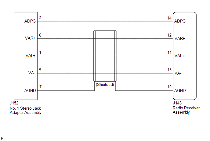
PROCEDURE
| 1. | CHECK HARNESS AND CONNECTOR (RADIO RECEIVER ASSEMBLY - NO. 1 STEREO JACK ADAPTER ASSEMBLY) |
(a) Disconnect the J148 radio receiver assembly connector.
(b) Disconnect the J152 No. 1 stereo jack adapter assembly connector.
(c) Measure the resistance according to the value(s) in the table below.
Standard Resistance:
| Tester Connection | Condition | Specified Condition |
|---|---|---|
| J148-14 (ADPG) - J152-2 (ADPG) | Always | Below 1 Ω |
| J148-10 (AGND) - J152-7 (AGND) | Always | Below 1 Ω |
| J148-12 (VAR+) - J152-6 (VAR+) | Always | Below 1 Ω |
| J148-11 (VAL+) - J152-1 (VAL+) | Always | Below 1 Ω |
| J148-13 (VA-) - J152-5 (VA-) | Always | Below 1 Ω |
| J148-14 (ADPG) or J152-2 (ADPG) - Body ground | Always | 10 kΩ or higher |
| J148-10 (AGND) or J152-7 (AGND) - Body ground | Always | 10 kΩ or higher |
| J148-12 (VAR+) or J152-6 (VAR+) - Body ground | Always | 10 kΩ or higher |
| J148-11 (VAL+) or J152-1 (VAL+) - Body ground | Always | 10 kΩ or higher |
| J148-13 (VA-) or J152-5 (VA-) - Body ground | Always | 10 kΩ or higher |
| OK |  | PROCEED TO NEXT SUSPECTED AREA SHOWN IN PROBLEM SYMPTOMS TABLE |
| NG | | REPAIR OR REPLACE HARNESS OR CONNECTOR |
 Sound Signal Circuit between Radio Receiver and Stereo Component Amplifier
DESCRIPTION The radio receiver assembly sends a sound signal to the stereo component amplifier assembly via this circuit. The sound signal that has been sent is amplified by the stereo component ampli ...
 Data Signal Circuit between Radio Receiver and Stereo Jack Adapter
DESCRIPTION The No. 1 stereo jack adapter assembly sends the sound data signal or image data signal from a USB device to the radio receiver assembly via this circuit. WIRING DIAGRAM PROCEDURE 1. ...
Other materials:
Lexus RX (RX 350L, RX450h) 2016-2026 Repair Manual > Lighting System (w/ Automatic Headlight Beam Level Control System): System Diagram
SYSTEM DIAGRAM HEADLIGHT ASSEMBLY CIRCUIT (for Multiple Beam Headlight) HEADLIGHT ASSEMBLY CIRCUIT (for Single Beam Headlight) ...
Lexus RX (RX 350L, RX450h) 2016-2026 Repair Manual > Pre-collision System: Lost Communication with Cruise Control Front Distance Range Sensor Missing Message (U023587)
DESCRIPTION The forward recognition camera and millimeter wave radar sensor assembly communicate via CAN communication. If a signal is not received from the millimeter wave radar sensor assembly, the forward recognition camera stores a DTC. DTC No. Detection Item DTC Detection Condition Tro ...
Lexus RX (RX 350L, RX450h) 2016-{YEAR} Owners Manual
- For your information
- Pictorial index
- For safety and security
- Instrument cluster
- Operation of each component
- Driving
- Lexus Display Audio system
- Interior features
- Maintenance and care
- When trouble arises
- Vehicle specifications
- For owners
Lexus RX (RX 350L, RX450h) 2016-{YEAR} Repair Manual

0.0101