
Lexus RX (RX 350L, RX450h) 2016-2026 Repair Manual: Sound Signal Circuit between Radio Receiver and Stereo Component Amplifier
DESCRIPTION
The radio receiver assembly sends a sound signal to the stereo component amplifier assembly via this circuit.
The sound signal that has been sent is amplified by the stereo component amplifier assembly, and then is sent to the speakers.
If there is an open or short in the circuit, sound cannot be heard from the speakers even if there is no malfunction in the stereo component amplifier assembly or speakers.
WIRING DIAGRAM
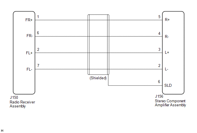
PROCEDURE
| 1. | CHECK HARNESS AND CONNECTOR (RADIO RECEIVER ASSEMBLY - STEREO COMPONENT AMPLIFIER ASSEMBLY) |
(a) Disconnect the J150 radio receiver assembly connector.
(b) Disconnect the J156 stereo component amplifier assembly connector.
(c) Measure the resistance according to the value(s) in the table below.
Standard Resistance:
| Tester Connection | Condition | Specified Condition |
|---|---|---|
| J150-1 (FR+) - J156-5 (R+) | Always | Below 1 Ω |
| J150-6 (FR-) - J156-4 (R-) | Always | Below 1 Ω |
| J150-2 (FL+) - J156-3 (L+) | Always | Below 1 Ω |
| J150-7 (FL-) - J156-2 (L-) | Always | Below 1 Ω |
| J156-6 (SLD) - Body ground | Always | 10 kΩ or higher |
| J150-1 (FR+) or J156-5 (R+) - Body ground | Always | 10 kΩ or higher |
| J150-6 (FR-) or J156-4 (R-) - Body ground | Always | 10 kΩ or higher |
| J150-2 (FL+) or J156-3 (L+) - Body ground | Always | 10 kΩ or higher |
| J150-7 (FL-) or J156-2 (L-) - Body ground | Always | 10 kΩ or higher |
| OK |  | PROCEED TO NEXT SUSPECTED AREA SHOWN IN PROBLEM SYMPTOMS TABLE |
| NG | | REPAIR OR REPLACE HARNESS OR CONNECTOR |
 Speaker Circuit
DESCRIPTION If there is a short in a speaker circuit, the stereo component amplifier assembly detects it and stops output to the speakers. Thus sound cannot be heard from the speakers even if there is ...
 Sound Signal Circuit between Radio Receiver and Stereo Jack Adapter
DESCRIPTION The No. 1 stereo jack adapter assembly sends the sound signal from an external device to the radio receiver assembly via this circuit. WIRING DIAGRAM PROCEDURE 1. CHECK HARNESS AND ...
Other materials:
Lexus RX (RX 350L, RX450h) 2016-2026 Repair Manual > Front Door Window Frame Moulding: Components
COMPONENTS ILLUSTRATION *1 FRONT DOOR FRONT WINDOW FRAME MOULDING *2 FRONT DOOR REAR WINDOW FRAME MOULDING *3 FRONT DOOR UPPER WINDOW FRAME MOULDING *4 FRONT DOOR WEATHERSTRIP *5 FRONT DOOR SUB-ASSEMBLY *6 RIVET N*m (kgf*cm, ft.*lbf): Specified torque ● Non ...
Lexus RX (RX 350L, RX450h) 2016-2026 Owners Manual > Using an external device: Using USB memory
device
Connecting a USB memory device enables you to enjoy music from the
vehicle
speakers.
Select "USB" or "USB2" on the audio source selection screen.
USB top screen
Pressing the "MEDIA" button displays the USB top screen from any screen of
the
selected source.
■ Selecting a file
Press the ...
Lexus RX (RX 350L, RX450h) 2016-{YEAR} Owners Manual
- For your information
- Pictorial index
- For safety and security
- Instrument cluster
- Operation of each component
- Driving
- Lexus Display Audio system
- Interior features
- Maintenance and care
- When trouble arises
- Vehicle specifications
- For owners
Lexus RX (RX 350L, RX450h) 2016-{YEAR} Repair Manual

0.0124