Lexus RX (RX 350L, RX450h) 2016-2026 Repair Manual: Speaker Circuit
DESCRIPTION
If there is a short in a speaker circuit, the stereo component amplifier assembly detects it and stops output to the speakers.
Thus sound cannot be heard from the speakers even if there is no malfunction in the stereo component amplifier assembly, DCM (telematics transceiver)* or speakers.
- *: w/ Manual (SOS) Switch
WIRING DIAGRAM
for 9 Speakers.png)
.png) for 12 Speakers
for 12 Speakers .png)
.png)
CAUTION / NOTICE / HINT
NOTICE:
-
Depending on the parts that are replaced during vehicle inspection or maintenance, performing initialization, registration or calibration may be needed. Refer to Precaution for Audio and Visual System.
Click here
.gif)
-
Before replacing the DCM (telematics transceiver), refer to Registration.
Click here
PROCEDURE
| 1. | CONFIRM MODEL |
(a) Choose the model to be inspected.
| Result | Proceed to |
|---|---|
| for 9 Speakers | A |
| for 12 Speakers | B |
| B | .gif) | GO TO STEP 16 |
|
.gif)
| 2. | CHECK SPEAKER (OPERATION CHECK) |
| (a) Enter the "System Check Mode" screen. Refer to Check SP Check On in Operation Check. Click here |
|
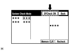
(b) Perform the operation check above and determine the speaker that is not operating.
| Not Operating Speaker | Proceed to |
|---|---|
| Front No. 3 speaker assembly (w/ Manual (SOS) Switch) | A |
| Front No. 3 speaker assembly (w/o Manual (SOS) Switch) | B |
| Front No. 2 speaker assembly | C |
| Front No. 1 speaker assembly | D |
| Rear speaker assembly or rear No. 2 speaker assembly | E |
HINT:
If sound cannot be heard from any speaker, inspect all of them.
| B | | GO TO STEP 6 |
| C | | GO TO STEP 8 |
| D | | GO TO STEP 10 |
| E | | GO TO STEP 12 |
|
| 3. | CHECK HARNESS AND CONNECTOR (STEREO COMPONENT AMPLIFIER ASSEMBLY, DCM (TELEMATICS TRANSCEIVER) - FRONT NO. 3 SPEAKER ASSEMBLY) |
(a) Disconnect the J66 stereo component amplifier assembly connector.
(b) Disconnect the J155 DCM (telematics transceiver) connector.
(c) Disconnect the K2 front No. 3 speaker assembly connector.
(d) Measure the resistance according to the value(s) in the table below.
Standard Resistance:
| Tester Connection | Condition | Specified Condition |
|---|---|---|
| J66-7 (CTR+) - J155-1 (SPI+) | Always | Below 1 Ω |
| J66-22 (CTR-) - J155-2 (SPI-) | Always | Below 1 Ω |
| K2-2 - J155-3 (SPO+) | Always | Below 1 Ω |
| K2-1 - J155-4 (SPO-) | Always | Below 1 Ω |
| J66-7 (CTR+) or J155-1 (SPI+) - Body ground | Always | 10 kΩ or higher |
| J66-22 (CTR-) or J155-2 (SPI-) - Body ground | Always | 10 kΩ or higher |
| K2-2 or J155-3 (SPO+) - Body ground | Always | 10 kΩ or higher |
| K2-1 or J155-4 (SPO-) - Body ground | Always | 10 kΩ or higher |
| NG | | REPAIR OR REPLACE HARNESS OR CONNECTOR |
|
| 4. | INSPECT FRONT NO. 3 SPEAKER ASSEMBLY |
(a) Remove the front No. 3 speaker assembly.
Click here
(b) Inspect the front No. 3 speaker assembly.
Click here
| NG | | REPLACE FRONT NO. 3 SPEAKER ASSEMBLY |
|
| 5. | INSPECT DCM (TELEMATICS TRANSCEIVER) |
(a) Remove the DCM (telematics transceiver).
Click here
| (b) Measure the resistance according to the value(s) in the table below. Standard Resistance:
|
|
.png)
| OK | | PROCEED TO NEXT SUSPECTED AREA SHOWN IN PROBLEM SYMPTOMS TABLE |
| NG | | REPLACE DCM (TELEMATICS TRANSCEIVER) |
| 6. | CHECK HARNESS AND CONNECTOR (STEREO COMPONENT AMPLIFIER ASSEMBLY - FRONT NO. 3 SPEAKER ASSEMBLY) |
(a) Disconnect the J66 stereo component amplifier assembly connector.
(b) Disconnect the K2 front No. 3 speaker assembly connector.
(c) Measure the resistance according to the value(s) in the table below.
Standard Resistance:
| Tester Connection | Condition | Specified Condition |
|---|---|---|
| J66-7 (CTR+) - K2-2 | Always | Below 1 Ω |
| J66-22 (CTR-) - K2-1 | Always | Below 1 Ω |
| J66-7 (CTR+) or K2-2 - Body ground | Always | 10 kΩ or higher |
| J66-22 (CTR-) or K2-1 - Body ground | Always | 10 kΩ or higher |
| NG | | REPAIR OR REPLACE HARNESS OR CONNECTOR |
|
| 7. | INSPECT FRONT NO. 3 SPEAKER ASSEMBLY |
(a) Remove the front No. 3 speaker assembly.
Click here
(b) Inspect the front No. 3 speaker assembly.
Click here
| OK | | PROCEED TO NEXT SUSPECTED AREA SHOWN IN PROBLEM SYMPTOMS TABLE |
| NG | | REPLACE FRONT NO. 3 SPEAKER ASSEMBLY |
| 8. | CHECK HARNESS AND CONNECTOR (STEREO COMPONENT AMPLIFIER ASSEMBLY - FRONT NO. 2 SPEAKER ASSEMBLY) |
(a) Disconnect the J66 stereo component amplifier assembly connector.
(b) Disconnect the K6 and K8 front No. 2 speaker assembly connectors.
(c) Measure the resistance according to the value(s) in the table below.
Standard Resistance:
| Tester Connection | Condition | Specified Condition |
|---|---|---|
| J66-13 (FR+) - K6-4 | Always | Below 1 Ω |
| J66-28 (FR-) - K6-2 | Always | Below 1 Ω |
| J66-12 (FL+) - K8-4 | Always | Below 1 Ω |
| J66-27 (FL-) - K8-2 | Always | Below 1 Ω |
| J66-13 (FR+) or K6-4 - Body ground | Always | 10 kΩ or higher |
| J66-28 (FR-) or K6-2 - Body ground | Always | 10 kΩ or higher |
| J66-12 (FL+) or K8-4 - Body ground | Always | 10 kΩ or higher |
| J66-27 (FL-) or K8-2 - Body ground | Always | 10 kΩ or higher |
| NG | | REPAIR OR REPLACE HARNESS OR CONNECTOR |
|
| 9. | INSPECT FRONT NO. 2 SPEAKER ASSEMBLY |
(a) Remove the front No. 2 speaker assembly.
Click here
(b) Inspect the front No. 2 speaker assembly.
Click here
OK:
Malfunction disappears.
| OK | | END |
| NG | | PROCEED TO NEXT SUSPECTED AREA SHOWN IN PROBLEM SYMPTOMS TABLE |
| 10. | CHECK HARNESS AND CONNECTOR (STEREO COMPONENT AMPLIFIER ASSEMBLY - FRONT NO. 1 SPEAKER ASSEMBLY) |
(a) Disconnect the J66 stereo component amplifier assembly connector.
(b) Disconnect the M3 and N3 front No. 1 speaker assembly connectors.
(c) Measure the resistance according to the value(s) in the table below.
Standard Resistance:
| Tester Connection | Condition | Specified Condition |
|---|---|---|
| J66-5 (WFR+) - M3-1 | Always | Below 1 Ω |
| J66-20 (WFR-) - M3-2 | Always | Below 1 Ω |
| J66-4 (WFL+) - N3-1 | Always | Below 1 Ω |
| J66-19 (WFL-) - N3-2 | Always | Below 1 Ω |
| J66-5 (WFR+) or M3-1 - Body ground | Always | 10 kΩ or higher |
| J66-20 (WFR-) or M3-2 - Body ground | Always | 10 kΩ or higher |
| J66-4 (WFL+) or N3-1 - Body ground | Always | 10 kΩ or higher |
| J66-19 (WFL-) or N3-2 - Body ground | Always | 10 kΩ or higher |
| NG | | REPAIR OR REPLACE HARNESS OR CONNECTOR |
|
| 11. | INSPECT FRONT NO. 1 SPEAKER ASSEMBLY |
(a) Remove the front No. 1 speaker assembly.
Click here
(b) Inspect the front No. 1 speaker assembly.
Click here
| OK | | PROCEED TO NEXT SUSPECTED AREA SHOWN IN PROBLEM SYMPTOMS TABLE |
| NG | | REPLACE FRONT NO. 1 SPEAKER ASSEMBLY |
| 12. | CHECK HARNESS AND CONNECTOR (STEREO COMPONENT AMPLIFIER ASSEMBLY - REAR NO. 2 SPEAKER ASSEMBLY) |
(a) Disconnect the J66 stereo component amplifier assembly connector.
(b) Disconnect the O5 and P5 rear No. 2 speaker assembly connectors.
(c) Measure the resistance according to the value(s) in the table below.
Standard Resistance:
| Tester Connection | Condition | Specified Condition |
|---|---|---|
| J66-9 (RR+) - O5-4 (+TW) | Always | Below 1 Ω |
| J66-24 (RR-) - O5-2 (-TW) | Always | Below 1 Ω |
| J66-8 (RL+) - P5-4 (+TW) | Always | Below 1 Ω |
| J66-23 (RL-) - P5-2 (-TW) | Always | Below 1 Ω |
| J66-9 (RR+) or O5-4 (+TW) - Body ground | Always | 10 kΩ or higher |
| J66-24 (RR-) or O5-2 (-TW) - Body ground | Always | 10 kΩ or higher |
| J66-8 (RL+) or P5-4 (+TW) - Body ground | Always | 10 kΩ or higher |
| J66-23 (RL-) or P5-2 (-TW) - Body ground | Always | 10 kΩ or higher |
| NG | | REPAIR OR REPLACE HARNESS OR CONNECTOR |
|
| 13. | CHECK HARNESS AND CONNECTOR (REAR SPEAKER ASSEMBLY - REAR NO. 2 SPEAKER ASSEMBLY) |
(a) Disconnect the O2 and P2 rear speaker assembly connectors.
(b) Disconnect the O5 and P5 rear No. 2 speaker assembly connectors.
(c) Measure the resistance according to the value(s) in the table below.
Standard Resistance:
| Tester Connection | Condition | Specified Condition |
|---|---|---|
| O2-1 - O5-3 (+) | Always | Below 1 Ω |
| O2-2 - O5-1 (-) | Always | Below 1 Ω |
| P2-1 - P5-3 (+) | Always | Below 1 Ω |
| P2-2 - P5-1 (-) | Always | Below 1 Ω |
| O2-1 or O5-3 (+) - Body ground | Always | 10 kΩ or higher |
| O2-2 or O5-1 (-) - Body ground | Always | 10 kΩ or higher |
| P2-1 or P5-3 (+) - Body ground | Always | 10 kΩ or higher |
| P2-2 or P5-1 (-) - Body ground | Always | 10 kΩ or higher |
| NG | | REPAIR OR REPLACE HARNESS OR CONNECTOR |
|
| 14. | INSPECT REAR SPEAKER ASSEMBLY |
(a) Remove the rear speaker assembly.
Click here
(b) Inspect the rear speaker assembly.
Click here
| NG | | REPLACE REAR SPEAKER ASSEMBLY |
|
| 15. | INSPECT REAR NO. 2 SPEAKER ASSEMBLY |
(a) Remove the rear No. 2 speaker assembly.
Click here
(b) Inspect the rear No. 2 speaker assembly.
Click here
OK:
Malfunction disappears.
| OK | | END |
| NG | | PROCEED TO NEXT SUSPECTED AREA SHOWN IN PROBLEM SYMPTOMS TABLE |
| 16. | CHECK SPEAKER (OPERATION CHECK) |
| (a) Enter the "System Check Mode" screen. Refer to Check SP Check On in Operation Check. Click here |
|
(b) Perform the operation check above and determine the speaker that is not operating.
| Not Operating Speaker | Proceed to |
|---|---|
| Front No. 3 speaker assembly (w/ Manual (SOS) Switch) | A |
| Front No. 3 speaker assembly (w/o Manual (SOS) Switch) | B |
| Front No. 2 speaker assembly | C |
| Front No. 1 speaker assembly | D |
| Rear speaker assembly or rear No. 2 speaker assembly | E |
| Rear No. 3 speaker assembly | F |
HINT:
If sound cannot be heard from any speaker, inspect all of them.
| B | | GO TO STEP 20 |
| C | | GO TO STEP 22 |
| D | | GO TO STEP 24 |
| E | | GO TO STEP 26 |
| F | | GO TO STEP 30 |
|
| 17. | CHECK HARNESS AND CONNECTOR (STEREO COMPONENT AMPLIFIER ASSEMBLY - DCM (TELEMATICS TRANSCEIVER) - FRONT NO. 3 SPEAKER ASSEMBLY) |
(a) Disconnect the J66 stereo component amplifier assembly connector.
(b) Disconnect the J155 DCM (telematics transceiver) connector.
(c) Disconnect the K2 front No. 3 speaker assembly connector.
(d) Measure the resistance according to the value(s) in the table below.
Standard Resistance:
| Tester Connection | Condition | Specified Condition |
|---|---|---|
| J66-7 (CTR+) - J155-1 (SPI+) | Always | Below 1 Ω |
| J66-22 (CTR-) - J155-2 (SPI-) | Always | Below 1 Ω |
| K2-2 - J155-3 (SPO+) | Always | Below 1 Ω |
| K2-1 - J155-4 (SPO-) | Always | Below 1 Ω |
| J66-7 (CTR+) or J155-1 (SPI+) - Body ground | Always | 10 kΩ or higher |
| J66-22 (CTR-) or J155-2 (SPI-) - Body ground | Always | 10 kΩ or higher |
| K2-2 or J155-3 (SPO+) - Body ground | Always | 10 kΩ or higher |
| K2-1 or J155-4 (SPO-) - Body ground | Always | 10 kΩ or higher |
| NG | | REPAIR OR REPLACE HARNESS OR CONNECTOR |
|
| 18. | INSPECT FRONT NO. 3 SPEAKER ASSEMBLY |
(a) Remove the front No. 3 speaker assembly.
Click here
(b) Inspect the front No. 3 speaker assembly.
Click here
| NG | | REPLACE FRONT NO. 3 SPEAKER ASSEMBLY |
|
| 19. | INSPECT DCM (TELEMATICS TRANSCEIVER) |
(a) Remove the DCM (telematics transceiver).
Click here
| (b) Measure the resistance according to the value(s) in the table below. Standard Resistance:
|
|
| OK | | PROCEED TO NEXT SUSPECTED AREA SHOWN IN PROBLEM SYMPTOMS TABLE |
| NG | | REPLACE DCM (TELEMATICS TRANSCEIVER) |
| 20. | CHECK HARNESS AND CONNECTOR (STEREO COMPONENT AMPLIFIER ASSEMBLY - FRONT NO. 3 SPEAKER ASSEMBLY) |
(a) Disconnect the J66 stereo component amplifier assembly connector.
(b) Disconnect the K2 front No. 3 speaker assembly connector.
(c) Measure the resistance according to the value(s) in the table below.
Standard Resistance:
| Tester Connection | Condition | Specified Condition |
|---|---|---|
| J66-7 (CTR+) - K2-2 | Always | Below 1 Ω |
| J66-22 (CTR-) - K2-1 | Always | Below 1 Ω |
| J66-7 (CTR+) or K2-2 - Body ground | Always | 10 kΩ or higher |
| J66-22 (CTR-) or K2-1 - Body ground | Always | 10 kΩ or higher |
| NG | | REPAIR OR REPLACE HARNESS OR CONNECTOR |
|
| 21. | INSPECT FRONT NO. 3 SPEAKER ASSEMBLY |
(a) Remove the front No. 3 speaker assembly.
Click here
(b) Inspect the front No. 3 speaker assembly.
Click here
| OK | | PROCEED TO NEXT SUSPECTED AREA SHOWN IN PROBLEM SYMPTOMS TABLE |
| NG | | REPLACE FRONT NO. 3 SPEAKER ASSEMBLY |
| 22. | CHECK HARNESS AND CONNECTOR (STEREO COMPONENT AMPLIFIER ASSEMBLY - FRONT NO. 2 SPEAKER ASSEMBLY) |
(a) Disconnect the J66 stereo component amplifier assembly connector.
(b) Disconnect the K5 and K7 front No. 2 speaker assembly connectors.
(c) Measure the resistance according to the value(s) in the table below.
Standard Resistance:
| Tester Connection | Condition | Specified Condition |
|---|---|---|
| J66-13 (FR+) - K5-2 | Always | Below 1 Ω |
| J66-28 (FR-) - K5-1 | Always | Below 1 Ω |
| J66-12 (FL+) - K7-2 | Always | Below 1 Ω |
| J66-27 (FL-) - K7-1 | Always | Below 1 Ω |
| J66-13 (FR+) or K5-2 - Body ground | Always | 10 kΩ or higher |
| J66-28 (FR-) or K5-1 - Body ground | Always | 10 kΩ or higher |
| J66-12 (FL+) or K7-2 - Body ground | Always | 10 kΩ or higher |
| J66-27 (FL-) or K7-1 - Body ground | Always | 10 kΩ or higher |
| NG | | REPAIR OR REPLACE HARNESS OR CONNECTOR |
|
| 23. | INSPECT FRONT NO. 2 SPEAKER ASSEMBLY |
(a) Remove the front No. 2 speaker assembly.
Click here
(b) Inspect the front No. 2 speaker assembly.
Click here
OK:
Malfunction disappears.
| OK | | END |
| NG | | PROCEED TO NEXT SUSPECTED AREA SHOWN IN PROBLEM SYMPTOMS TABLE |
| 24. | CHECK HARNESS AND CONNECTOR (STEREO COMPONENT AMPLIFIER ASSEMBLY - FRONT NO. 1 SPEAKER ASSEMBLY) |
(a) Disconnect the J66 stereo component amplifier assembly connector.
(b) Disconnect the M3 and N3 front No. 1 speaker assembly connectors.
(c) Measure the resistance according to the value(s) in the table below.
Standard Resistance:
| Tester Connection | Condition | Specified Condition |
|---|---|---|
| J66-5 (WFR+) - M3-1 | Always | Below 1 Ω |
| J66-20 (WFR-) - M3-2 | Always | Below 1 Ω |
| J66-4 (WFL+) - N3-1 | Always | Below 1 Ω |
| J66-19 (WFL-) - N3-2 | Always | Below 1 Ω |
| J66-5 (WFR+) or M3-1 - Body ground | Always | 10 kΩ or higher |
| J66-20 (WFR-) or M3-2 - Body ground | Always | 10 kΩ or higher |
| J66-4 (WFL+) or N3-1 - Body ground | Always | 10 kΩ or higher |
| J66-19 (WFL-) or N3-2 - Body ground | Always | 10 kΩ or higher |
| NG | | REPAIR OR REPLACE HARNESS OR CONNECTOR |
|
| 25. | INSPECT FRONT NO. 1 SPEAKER ASSEMBLY |
(a) Remove the front No. 1 speaker assembly.
Click here
(b) Inspect the front No. 1 speaker assembly.
Click here
| OK | | PROCEED TO NEXT SUSPECTED AREA SHOWN IN PROBLEM SYMPTOMS TABLE |
| NG | | REPLACE FRONT NO. 1 SPEAKER ASSEMBLY |
| 26. | CHECK HARNESS AND CONNECTOR (STEREO COMPONENT AMPLIFIER ASSEMBLY - REAR NO. 2 SPEAKER ASSEMBLY) |
(a) Disconnect the J66 stereo component amplifier assembly connector.
(b) Disconnect the O5 and P5 rear No. 2 speaker assembly connectors.
(c) Measure the resistance according to the value(s) in the table below.
Standard Resistance:
| Tester Connection | Condition | Specified Condition |
|---|---|---|
| J66-9 (RR+) - O5-4 (+TW) | Always | Below 1 Ω |
| J66-24 (RR-) - O5-2 (-TW) | Always | Below 1 Ω |
| J66-8 (RL+) - P5-4 (+TW) | Always | Below 1 Ω |
| J66-23 (RL-) - P5-2 (-TW) | Always | Below 1 Ω |
| J66-9 (RR+) or O5-4 (+TW) - Body ground | Always | 10 kΩ or higher |
| J66-24 (RR-) or O5-2 (-TW) - Body ground | Always | 10 kΩ or higher |
| J66-8 (RL+) or P5-4 (+TW) - Body ground | Always | 10 kΩ or higher |
| J66-23 (RL-) or P5-2 (-TW) - Body ground | Always | 10 kΩ or higher |
| NG | | REPAIR OR REPLACE HARNESS OR CONNECTOR |
|
| 27. | CHECK HARNESS AND CONNECTOR (REAR SPEAKER ASSEMBLY - REAR NO. 2 SPEAKER ASSEMBLY) |
(a) Disconnect the O2 and P2 rear speaker assembly connectors.
(b) Disconnect the O5 and P5 rear No. 2 speaker assembly connectors.
(c) Measure the resistance according to the value(s) in the table below.
Standard Resistance:
| Tester Connection | Condition | Specified Condition |
|---|---|---|
| O2-1 - O5-3 (+) | Always | Below 1 Ω |
| O2-2 - O5-1 (-) | Always | Below 1 Ω |
| P2-1 - P5-3 (+) | Always | Below 1 Ω |
| P2-2 - P5-1 (-) | Always | Below 1 Ω |
| O2-1 or O5-3 (+) - Body ground | Always | 10 kΩ or higher |
| O2-2 or O5-1 (-) - Body ground | Always | 10 kΩ or higher |
| P2-1 or P5-3 (+) - Body ground | Always | 10 kΩ or higher |
| P2-2 or P5-1 (-) - Body ground | Always | 10 kΩ or higher |
| NG | | REPAIR OR REPLACE HARNESS OR CONNECTOR |
|
| 28. | INSPECT REAR SPEAKER ASSEMBLY |
(a) Remove the rear speaker assembly.
Click here
(b) Inspect the rear speaker assembly.
Click here
| NG | | REPLACE REAR SPEAKER ASSEMBLY |
|
| 29. | INSPECT REAR NO. 2 SPEAKER ASSEMBLY |
(a) Remove the rear No. 2 speaker assembly.
Click here
(b) Inspect the rear No. 2 speaker assembly.
Click here
OK:
Malfunction disappears.
| OK | | END |
| NG | | PROCEED TO NEXT SUSPECTED AREA SHOWN IN PROBLEM SYMPTOMS TABLE |
| 30. | CHECK HARNESS AND CONNECTOR (STEREO COMPONENT AMPLIFIER ASSEMBLY - REAR NO. 3 SPEAKER ASSEMBLY) |
(a) Disconnect the J66 stereo component amplifier assembly connector.
(b) Disconnect the S53 rear No. 3 speaker assembly connector.
(c) Measure the resistance according to the value(s) in the table below.
Standard Resistance:
| Tester Connection | Condition | Specified Condition |
|---|---|---|
| J66-6 (WF1+) - S53-1 | Always | Below 1 Ω |
| J66-21 (WF1-) - S53-2 | Always | Below 1 Ω |
| J66-6 (WF1+) or S53-1 - Body ground | Always | 10 kΩ or higher |
| J66-21 (WF1-) or S53-2 - Body ground | Always | 10 kΩ or higher |
| NG | | REPAIR OR REPLACE HARNESS OR CONNECTOR |
|
| 31. | INSPECT REAR NO. 3 SPEAKER ASSEMBLY |
(a) Remove the rear No. 3 speaker assembly.
w/o Rear No. 2 Seat: Click here
w/ Rear No. 2 Seat: Click here
(b) Inspect the rear No. 3 speaker assembly.
w/o Rear No. 2 Seat: Click here
w/ Rear No. 2 Seat: Click here
| OK | | PROCEED TO NEXT SUSPECTED AREA SHOWN IN PROBLEM SYMPTOMS TABLE |
| NG | | REPLACE REAR NO. 3 SPEAKER ASSEMBLY |
 Illumination Circuit
DESCRIPTION Power is supplied to the radio receiver assembly and steering pad switch assembly illumination when the light control switch is in the tail or head position. WIRING DIAGRAM CAUTION / NOTI ...
 Sound Signal Circuit between Radio Receiver and Stereo Component Amplifier
DESCRIPTION The radio receiver assembly sends a sound signal to the stereo component amplifier assembly via this circuit. The sound signal that has been sent is amplified by the stereo component ampli ...
Other materials:
Lexus RX (RX 350L, RX450h) 2016-2026 Repair Manual > Front Radar Sensor System: Freeze Frame Data
FREEZE FRAME DATA DESCRIPTION (a) Whenever a front radar sensor system DTC is stored, the millimeter wave radar sensor assembly stores the current vehicle state as Freeze Frame Data. CHECK FREEZE FRAME DATA (a) Connect the Techstream to the DLC3. (b) Turn the engine switch on (IG). (c) Turn the Tech ...
Lexus RX (RX 350L, RX450h) 2016-2026 Owners Manual > Driving procedures: Power (ignition) switch
Performing the following operations when carrying the electronic key on
your
person starts the hybrid system or changes power switch modes.
Starting the hybrid system
1. Check that the parking brake is set.
2. Check that the shift lever is in P.
3. Firmly depress the brake pedal.
and a
...
Lexus RX (RX 350L, RX450h) 2016-{YEAR} Owners Manual
- For your information
- Pictorial index
- For safety and security
- Instrument cluster
- Operation of each component
- Driving
- Lexus Display Audio system
- Interior features
- Maintenance and care
- When trouble arises
- Vehicle specifications
- For owners
Lexus RX (RX 350L, RX450h) 2016-{YEAR} Repair Manual

0.0253